Service Manual HS60.pdf - 第106页
4 G ant ri es HS- 6 0 S erv ice Ma nu al 4. 7 R ep laci ng th e X -ax is sc al e (0 03 293 16 -01 ) 03/ 200 3 US I ssue 104 Æ Lo osen t he M 8x20 hexagon soc ket-head scr ew in the hole in t he elast omeric s pring. Æ P …
HS-60 Service Manual 4 Gantries
03/2003 US Issue 4.6 Replacing the elastomeric spring (00301040-01)
103
4.6 Replacing the elastomeric spring (00301040-01)
4.6.1 Tools and equipment
– Set of DIN 911 Allen keys
4.6.2 Parts
25x10.5x50 elastomeric spring, from item number 00301040-01 4
4.6.3 Removing the elastomeric spring
Æ
Switch the placement system off and secure it to prevent switching on again as described in
Section 4.4
, page 100 onward.
DANGER POWERFUL MAGNETIC FIELD 4
Always follow the special safety instructions when working in the vicinity of powerful magnetic
fields (see Section 4.5, page 101 onward). 4
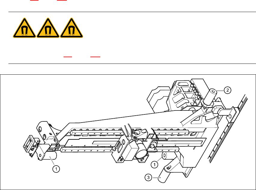
Fig. 4.6 - 1 Replacing the elastomeric spring
Key
1 Elastomeric springs for the X-gantry
2 Gantries 1 and 3: elastomeric spring for the Y-axis
Gantries 2 and 4: reflecting bracket instead of elastomeric spring
3 Gantries 1 and 3: elastomeric spring for the Y-axis
Gantries 2 and 4: item 3 canceled 4
4 Gantries HS-60 Service Manual
4.7 Replacing the X-axis scale (00329316-01) 03/2003 US Issue
104
Æ Loosen the M8x20 hexagon socket-head screw in the hole in the elastomeric spring.
Æ Push the metal sleeve out of the elastomeric spring.
4.6.4 Installing the elastomeric spring
Æ Insert the metal sleeve into the new elastomeric spring.
Æ Use the M8 x 20 hexagon socket-head screw to fix the elastomeric spring.
4.6.5 Settings
None 4
4.7 Replacing the X-axis scale (00329316-01)
4.7.1 Tools and equipment
– Set of DIN 911 Allen keys
– Spacer gauge
– SITEST program
4.7.2 Parts
X-axis scale for the HS-60, from item number 00329316-01 4
HS-60 Service Manual 4 Gantries
03/2003 US Issue 4.7 Replacing the X-axis scale (00329316-01)
105
4.7.3 Removing the X-axis scale
4
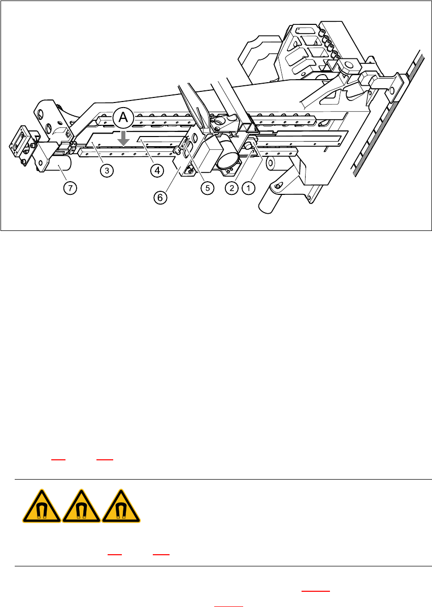
Fig. 4.7 - 1 Replacing the X-axis scale
Key
(1) Incremental encoder, X-axis
(2) 2 x M3 x 8 hexagon socket-head screws
(3) 11 x M2.5 x 5 hexagon socket-head screws with washers
(4) Scale, X-axis
(5) Proximity switch B1 and B2 for the X-axis
(6) Head mount
(7) Elastomeric spring
A Stop for the scale on the bars 4
Æ Switch the placement system off and secure it to prevent switching on again as described in
Section 4.4
, page 100 onward.
DANGER POWERFUL MAGNETIC FIELD 4
Always follow the special safety instructions when working in the vicinity of powerful magnetic
fields (see Section 4.5, page 101 onward). 4
Æ Loosen two M3 x 8 hexagon socket-head screws (item 2 in Fig. 4.7 - 1) to remove the incre-
mental encoder for the X-axis (item 1 in Fig. 4.7 - 1
).