Service Manual HS60.pdf - 第110页
4 G ant ri es HS- 6 0 S erv ice Ma nu al 4.8 R e plac ing t he tens ioni ng key s (00329 478-0 1, 00 3294 85-0 1) 03/20 03 US Is sue 108 4 Fig . 4 .8 - 1 Repla cing t he tens ioni ng key s Key (1) T ensioning key (2) T e…

HS-60 Service Manual 4 Gantries
03/2003 US Issue 4.8 Replacing the tensioning keys (00329478-01, 00329485-01)
107
4.8 Replacing the tensioning keys (00329478-01,
00329485-01)
4.8.1 Tools and equipment
– Set of DIN 911 Allen keys
– TSM belt tension measuring device, from item number 00326015-01
– "Measuring belt tensions" operating instructions
4.8.2 Parts
Designation From item number Item in Fig. 4.8 - 1
Tensioning key 00329478-01 (1)
Tensioning key 00329485-01 (2) 4
4.8.3 Removing the tensioning keys
Æ Switch the placement system off and secure it to prevent switching on again as described in
Section 4.4
, page 100 onward.
Æ Push the head mount towards the deflection pulley (item 6 in Fig. 4.8 - 1).
Æ To slacken the toothed belt (item 5 in Fig. 4.8 - 1)
– loosen the locknut (item 11 in Fig. 4.8 - 1
) and
– turn the hexagon socket-head screw counter-clockwise (item 3 in Fig. 4.8 - 1
).
Removing the tensioning key, item 1 (synchronizing disk, short) 4
Æ Loosen the M4 x 5 hexagon socket-head screw (item 8 in Fig. 4.8 - 1).
Æ Lift out the tensioning key.
Removing the tensioning key, item 2 (synchronizing disk, long) 4
Æ Unscrew the hexagon socket-head screw (item 3 in Fig. 4.8 - 1) from the spacer bolt (item 7 in
Fig. 4.8 - 1
).
Æ Lift out the tensioning key.
4 Gantries HS-60 Service Manual
4.8 Replacing the tensioning keys (00329478-01, 00329485-01) 03/2003 US Issue
108
4
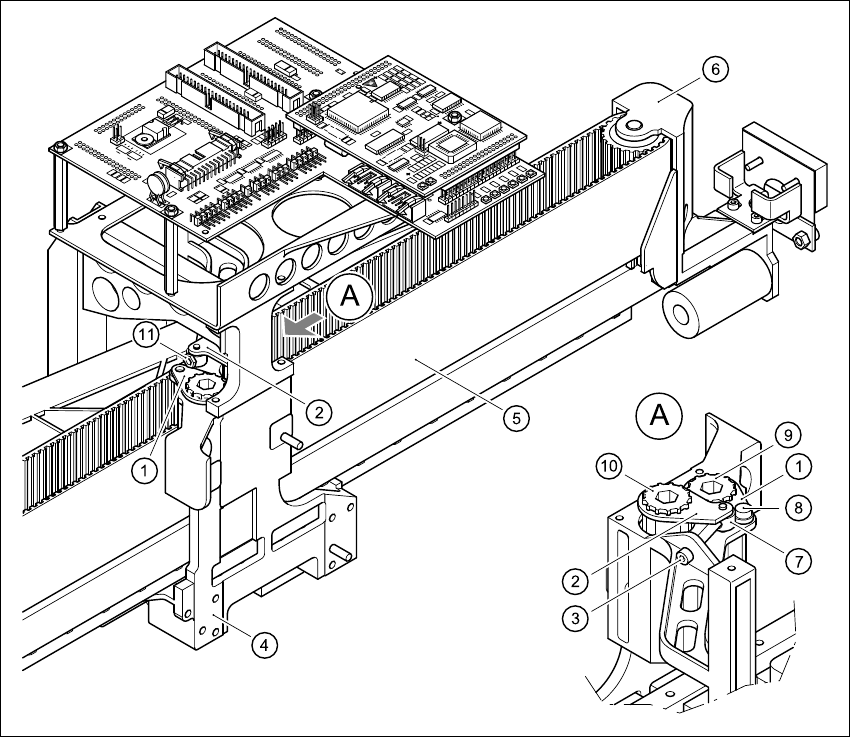
Fig. 4.8 - 1 Replacing the tensioning keys
Key
(1) Tensioning key
(2) Tensioning key
(3) M4 x 35 hexagon socket-head screw for tensioning the toothed belt
(4) Head mount
(5) Toothed belt for the X-axis
(6) Deflection pulley
(7) Spacer bolt with Benzing U-clip
(8) M4 x 5 hexagon socket-head screw
(9) Synchronizing disk, short
(10) Synchronizing disk, long
(11) Locknut
HS-60 Service Manual 4 Gantries
03/2003 US Issue 4.8 Replacing the tensioning keys (00329478-01, 00329485-01)
109
4.8.4 Installing the tensioning keys
Installing the tensioning key, item 1 (synchronizing disk, short) 4
Æ Place the tensioning key on the ’short’ synchronizing disk (item 9 in Fig. 4.8 - 1).
Æ Use the M4 x 5 hexagon socket-head screw (item 8 in Fig. 4.8 - 1) to fix the tensioning key.
Installing the tensioning key, item 2 (synchronizing disk, long) 4
Æ Fit the spacer bolt with the Benzing U-clip (item 7 in Fig. 4.8 - 1) on the new tensioning key.
Æ Place the tensioning key on the ’long’ synchronizing disk (item 10 in Fig. 4.8 - 1).
Æ Use the size 8 Allen key to turn the synchronizing disk slightly until the hexagon socket-head
screw (item 3 in Fig. 4.8 - 1
) can be screwed in.
Æ Pre-tension the toothed belt by turning the hexagon socket-head screw clockwise.
4.8.5 Settings
Æ Push the head mount towards the X-axis motor as far as the stop on the elastomeric spring.
Æ Turn the hexagon socket-head screw to set the belt tension to 53 Hz + 1/-3 Hz.
CAUTION 4
Do not overstretch the toothed belt when adjusting the belt tension. 4
Æ Secure the hexagon socket-head screw (item 3 in Fig. 4.8 - 1) with the locknut (item 11 in Fig.
4.8 - 1
).