Service Manual HS60.pdf - 第113页
HS -60 Se rvic e Manu al 4 Ga ntr ies 03/ 2003 US Issu e 4.9 Repl acin g the def lect ion uni t (003 3093 8-02) 111 F ig . 4. 9 - 1 R ep la ci ng t he d e fle ct io n u ni t Key (1) M 4 x 35 hexagon socket-head screw (2)…

4 Gantries HS-60 Service Manual
4.9 Replacing the deflection unit (00330938-02) 03/2003 US Issue
110
4.9 Replacing the deflection unit (00330938-02)
4.9.1 Tools and equipment
– Set of DIN 911 Allen keys
– TSM belt tension measuring device, from item number 00326015-01
– "Measuring belt tensions" operating instructions
4.9.2 Parts
Deflection unit X, from item number 00330938-01 4
4.9.3 Removing the deflection unit
Æ Switch the placement system off and secure it to prevent switching on again as described in
Section 4.4
, page 100 onward.
Æ To slacken the toothed belt (item 9 in Fig. 4.9 - 1)
– loosen the locknut (item 11 in Fig. 4.9 - 1
) and
– turn the hexagon socket-head screw counter-clockwise (item 1 in Fig. 4.9 - 1
).
Æ Remove the M4 x 35 hexagon socket-head screw (item 1 in Fig. 4.9 - 1).
Æ Remove the tensioning key (item 2 in Fig. 4.9 - 1) from the synchronizing disk (item 3 in Fig.
4.9 - 1
).
Æ Pull the toothed belt (item 9 in Fig. 4.9 - 1) out through the opening in the tension jack (item 4
in Fig. 4.9 - 1
).
Æ Unthread the toothed belt from the deflection unit (item 8 in Fig. 4.9 - 1).
Æ Loosen the two M3 x 8 hexagon socket-head screws (item 6 in Fig. 4.9 - 1) and remove the y
brake ’external’ (item 5 in Fig. 4.9 - 1
).
Æ Loosen the two M6 x 10 hexagon socket-head screws (item 7 in Fig. 4.9 - 1) and remove the
deflection unit ’X’ (item 8 in Fig. 4.9 - 1
).
Æ Remove the elastomeric spring (item 10 in Fig. 4.9 - 1) from the deflection unit.
HS-60 Service Manual 4 Gantries
03/2003 US Issue 4.9 Replacing the deflection unit (00330938-02)
111
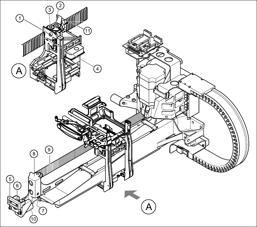
Fig. 4.9 - 1 Replacing the deflection unit
Key
(1) M4 x 35 hexagon socket-head screw (2) Tensioning key
(3) Synchronizing disk, long (4) Opening in tension jack for toothed belt
(5) Y-axis brake, external (6) 2 x M3 x 8 hexagon socket-head screws
(7) 2 x M6 x 10 hexagon socket-head screws (8) Deflection unit - X
(9) Synchroflex toothed belt (10) 25 x 10.5 x 50 elastomeric spring
(11) Locknut 4
4 Gantries HS-60 Service Manual
4.9 Replacing the deflection unit (00330938-02) 03/2003 US Issue
112
4.9.4 Installing the deflection unit ’X’
Æ Fit the elastomeric spring (item 10 in Fig. 4.9 - 1) on the new deflection unit (item 8 in Fig.
4.9 - 1
).
Æ Use the two M6 x 10 hexagon socket-head screws (item 7 in Fig. 4.9 - 1) to fix the deflection
unit (item 8 in Fig. 4.9 - 1
) to the gantry.
Æ Align the ’external’ brake (item 5 in Fig. 4.9 - 1) so that it is parallel with the braking surface and
fix to the deflection unit (item 8 in Fig. 4.9 - 1
) using the two M3 x 8 hexagon socket-head
screws.
Æ Place the toothed belt (item 9 in Fig. 4.9 - 1) around the synchronizing disk of the deflection
unit (item 8 in Fig. 4.9 - 1
).
PLEASE NOTE 4
See Fig. 4.9 - 2, page 113 onward, for the following assembly steps. 4
Æ Feed the toothed belt into the opening (item 3 in Fig. 4.9 - 2) in the tension jack (item 2 in Fig.
4.9 - 2
) so that it runs approximately 270° around the ’long’ synchronizing disk (item 4 in Fig.
4.9 - 2
).
Æ Place the tensioning key (item 5 in Fig. 4.9 - 2) on the synchronizing disk (item 4 in Fig.
4.9 - 2
).
Æ Use a size 8 Allen key to turn the synchronizing disk (item 4 in Fig. 4.9 - 2) clockwise.
Æ Screw the hexagon socket-head screw (item 7 in Fig. 4.9 - 2) into the threaded hole in the
spacer bolt (item 6 in Fig. 4.9 - 2
) and pre-tension the X-axis toothed belt.
4.9.5 Settings
Æ
Push the head mount (item 1 in Fig. 4.9 - 2) towards X-axis motor unit as far as the stop on the
elastomeric spring.
Æ Turn the hexagon socket-head screw (item 7 in Fig. 4.9 - 2) to set the belt tension to
53 Hz + 1/-3 Hz.
CAUTION 4
Do not overstretch the toothed belt when adjusting the belt tension. 4
Æ Secure the hexagon socket-head screw (item 7 in Fig. 4.9 - 2) with the locknut (item 8 in Fig.
4.9 - 2
).