Service Manual HS60.pdf - 第115页
HS -60 Se rvic e Manu al 4 Ga ntr ies 03/ 2003 US Issu e 4.9 Repl acin g the def lect ion uni t (003 3093 8-02) 113 4 Fig. 4.9 - 2 Fitti ng th e tooth ed bel t on the t e nsio n jack Key (1) Head mount (2) T ension jack …
4 Gantries HS-60 Service Manual
4.9 Replacing the deflection unit (00330938-02) 03/2003 US Issue
112
4.9.4 Installing the deflection unit ’X’
Æ Fit the elastomeric spring (item 10 in Fig. 4.9 - 1) on the new deflection unit (item 8 in Fig.
4.9 - 1
).
Æ Use the two M6 x 10 hexagon socket-head screws (item 7 in Fig. 4.9 - 1) to fix the deflection
unit (item 8 in Fig. 4.9 - 1
) to the gantry.
Æ Align the ’external’ brake (item 5 in Fig. 4.9 - 1) so that it is parallel with the braking surface and
fix to the deflection unit (item 8 in Fig. 4.9 - 1
) using the two M3 x 8 hexagon socket-head
screws.
Æ Place the toothed belt (item 9 in Fig. 4.9 - 1) around the synchronizing disk of the deflection
unit (item 8 in Fig. 4.9 - 1
).
PLEASE NOTE 4
See Fig. 4.9 - 2, page 113 onward, for the following assembly steps. 4
Æ Feed the toothed belt into the opening (item 3 in Fig. 4.9 - 2) in the tension jack (item 2 in Fig.
4.9 - 2
) so that it runs approximately 270° around the ’long’ synchronizing disk (item 4 in Fig.
4.9 - 2
).
Æ Place the tensioning key (item 5 in Fig. 4.9 - 2) on the synchronizing disk (item 4 in Fig.
4.9 - 2
).
Æ Use a size 8 Allen key to turn the synchronizing disk (item 4 in Fig. 4.9 - 2) clockwise.
Æ Screw the hexagon socket-head screw (item 7 in Fig. 4.9 - 2) into the threaded hole in the
spacer bolt (item 6 in Fig. 4.9 - 2
) and pre-tension the X-axis toothed belt.
4.9.5 Settings
Æ
Push the head mount (item 1 in Fig. 4.9 - 2) towards X-axis motor unit as far as the stop on the
elastomeric spring.
Æ Turn the hexagon socket-head screw (item 7 in Fig. 4.9 - 2) to set the belt tension to
53 Hz + 1/-3 Hz.
CAUTION 4
Do not overstretch the toothed belt when adjusting the belt tension. 4
Æ Secure the hexagon socket-head screw (item 7 in Fig. 4.9 - 2) with the locknut (item 8 in Fig.
4.9 - 2
).
HS-60 Service Manual 4 Gantries
03/2003 US Issue 4.9 Replacing the deflection unit (00330938-02)
113
4
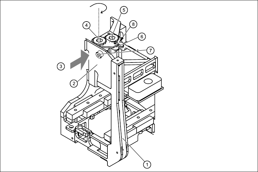
Fig. 4.9 - 2 Fitting the toothed belt on the tension jack
Key
(1) Head mount
(2) Tension jack for the toothed belt
(3) Opening for threading the toothed belt
(4) Synchronizing disk, long
(5) Tensioning key
(6) Spacer bolt with M4 threaded hole
(7) M4 x 35 hexagon socket-head screw for tensioning the toothed belt
(8) Locknut
4 Gantries HS-60 Service Manual
4.10 Replacing the X-axis toothed belt (00331076-02) 03/2003 US Issue
114
4.10 Replacing the X-axis toothed belt (00331076-02)
4.10.1 Tools and equipment
– Set of DIN 911 Allen keys
– TSM belt tension measuring device, from item number 00326015-01
– "Measuring belt tensions" operating instructions
4.10.2 Parts
Toothed belt, Synchroflex 50 ATS5-1205 E9-11, from item number 00331076-01 4
4.10.3 Removing the X-axis toothed belt
Æ Switch the placement system off and secure it to prevent switching on again as described in
Section 4.4
, page 100 onward.
DANGER POWERFUL MAGNETIC FIELD 4
Always follow the special safety instructions when working in the vicinity of powerful magnetic
fields (see Section 4.5, page 101 onward). 4
Æ Dismantle the two tensioning keys (item 1 in Fig. 4.10 - 1) (see Section 4.8.3)
Æ Remove the toothed belt from the two synchronizing disks (item 2 in Fig. 4.10 - 1).
Æ Unthread the toothed belt from the deflection unit (item 4 in Fig. 4.10 - 1).
Æ Remove the toothed belt from the synchronizing disk of the X-axis motor unit (item 5 in Fig.
4.10 - 1
).