Service Manual HS60.pdf - 第118页
4 G ant ri es HS- 6 0 S erv ice Ma nu al 4. 10 R epl ac in g t he X-a xi s to oth ed b el t (0 03 31 076- 02 ) 03/ 200 3 US I ssue 116 4.10.4 In st alling th e X-axis to o thed belt Æ P lace t he toothed belt around the …
HS-60 Service Manual 4 Gantries
03/2003 US Issue 4.10 Replacing the X-axis toothed belt (00331076-02)
115
4
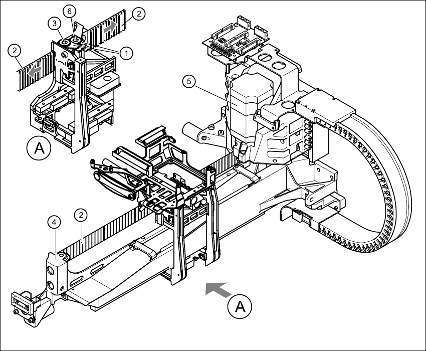
Fig. 4.10 - 1 Removing the X-axis toothed belt
Key
(1) Tensioning key
(2) Toothed belt
(3) Synchronizing disk, long
(4) Deflection unit X
(5) X-axis motor unit
(6) Synchronizing disk, short
4 Gantries HS-60 Service Manual
4.10 Replacing the X-axis toothed belt (00331076-02) 03/2003 US Issue
116
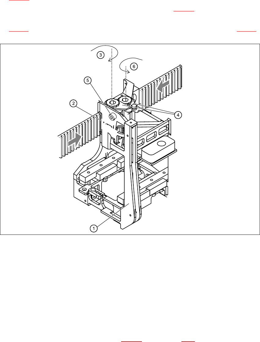
4.10.4 Installing the X-axis toothed belt
Æ Place the toothed belt around the synchronizing disk of the X-axis motor unit (item 5 in Fig.
4.10 - 1
).
Æ Thread the toothed belt into the deflection unit (item 4 in Fig. 4.10 - 1).
Æ Thread the two ends of the toothed belt into the openings on the tension jack (item 2 in Fig.
4.10 - 2
) until it runs approximately 270° around the synchronizing disks (item 3 in Fig. 4.10 - 2).
4
Fig. 4.10 - 2 Fixing the X-axis toothed belt to the tension jack
Key
(1) Head mount
(2) Tension jack
(3) Synchronizing disk, long
(4) Tensioning keys
(5) Hexagon socket-head screw for tensioning the toothed belt
(6) Synchronizing disk, short
Æ Fit the two tensioning keys (item 4 in Fig. 4.10 - 2) (see Section 4.8.4).

HS-60 Service Manual 4 Gantries
03/2003 US Issue 4.10 Replacing the X-axis toothed belt (00331076-02)
117
4.10.5 Settings
Æ Push the head mount (item 1 in Fig. 4.10 - 2) towards the X-axis motor unit as far as the stop
on the elastomeric spring.
Æ Turn the hexagon socket-head screw (item 5 in Fig. 4.10 - 2) to set the belt tension to
53 Hz + 1/-3 Hz.
CAUTION 4
Do not overstretch the toothed belt when adjusting the belt tension. 4
Æ Secure the hexagon socket-head screw (item 5 in Fig. 4.10 - 2) with the locknut.