Service Manual HS60.pdf - 第122页
4 G ant ri es HS- 6 0 S erv ice Ma nu al 4. 11 R epl ac in g t he X-a xi s m oto r u ni t (0 03 33 167- 03) 03/ 200 3 US I ssue 120 F ig. 4. 1 1 - 1 Repl ac ing th e X -ax is m otor unit Key (1) Head mount (2) M4 x 35 h …

HS-60 Service Manual 4 Gantries
03/2003 US Issue 4.11 Replacing the X-axis motor unit (00333167-03)
119
Æ To slacken the toothed belt (item 3 in Fig. 4.11 - 1)
– loosen the locknut (item 8 in Fig. 4.11 - 1
) and
– turn the hexagon socket-head screw counter-clockwise (item 2 in Fig. 4.11 - 1
).
Æ Loosen the two M6x14 socket head screws (item 7 in Fig. 4.11 - 1) for clamping the X-axis mo-
tor unit (item 4 in Fig. 4.11 - 1
).
Æ Pull the X-axis motor unit (item 4 in Fig. 4.11 - 1) up and out, at the same time pushing the
board holder slightly to the side.
4
Gantry 2 or 4 4
Æ Remove the black cover strip on the cross-beam above the gantry concerned:
– Remove the fan cable from the socket. The fan is fixed to the black cover strip.
– Remove the black cover strip (3 M6x8 hexagon socket-head screws).
Æ Cut the cable ties holding the X-axis motor cable.
Æ Remove the cable clamp for the flat ribbon cable (item 11 in Fig. 4.11 - 1)
Æ Unplug the X-motor plug from the X/Y distributor (item 5 in Fig. 4.11 - 1).
Æ Remove the board holder for the X/Y distributor (item 9 in Fig. 4.11 - 1).
Æ Remove the cable holder (item 10 in Fig. 4.11 - 1) for the trailing cable.
Æ To slacken the toothed belt (item 3 in Fig. 4.11 - 1)
– loosen the locknut (item 8 in Fig. 4.11 - 1
) and
– turn the hexagon socket-head screw counter-clockwise (item 2 in Fig. 4.11 - 1
).
Æ Loosen the two M6x14 socket head screws (item 7 in Fig. 4.11 - 1) for clamping the X-axis mo-
tor unit (item 4 in Fig. 4.11 - 1
).
Æ Pull the X-axis motor unit (item 4 in Fig. 4.11 - 1) up and out, at the same time pushing the
board holder slightly to the side.
4 Gantries HS-60 Service Manual
4.11 Replacing the X-axis motor unit (00333167-03) 03/2003 US Issue
120
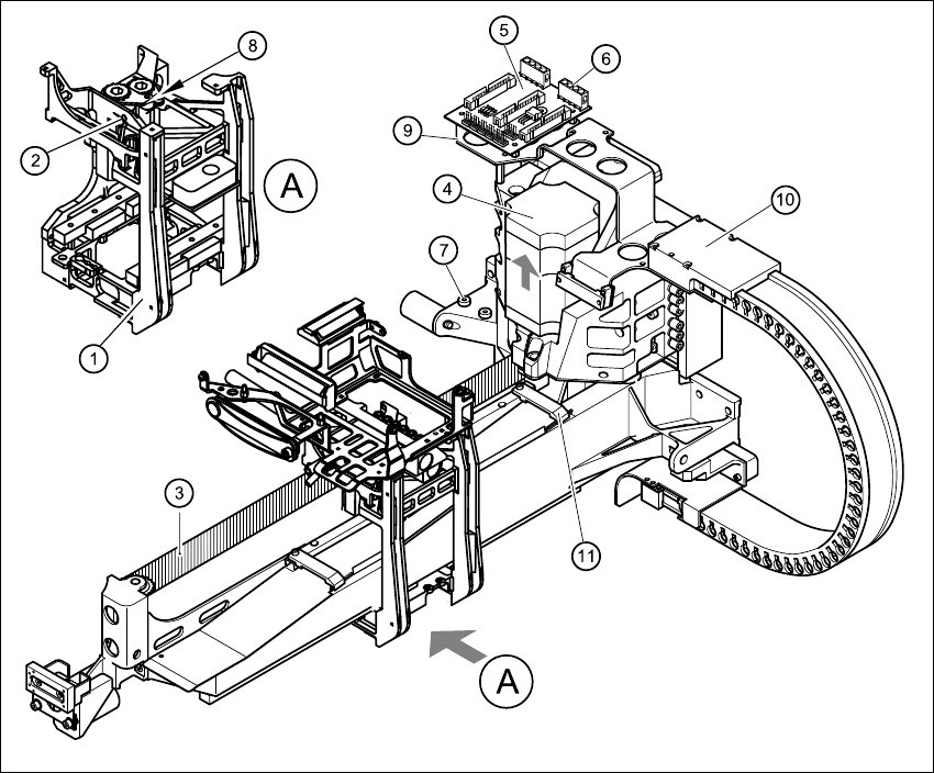
Fig. 4.11 - 1 Replacing the X-axis motor unit
Key
(1) Head mount
(2) M4 x 35 hexagon socket-head screw for tensioning the X-axis toothed belt
(3) Synchroflex X-axis toothed belt
(4) X-axis motor unit
(5) X/Y distributor
(6) X5 socket for X-axis motor
(7) 2 x M6 x 14 hexagon socket-head screws
(8) Locknut
(9) Board holder
(10) Cable holder
(11) Cable clamp
HS-60 Service Manual 4 Gantries
03/2003 US Issue 4.11 Replacing the X-axis motor unit (00333167-03)
121
4.11.4 Installing the X-axis motor unit
Gantry 1 or 3 4
Æ Carefully insert the X-axis motor unit (item 4 in Fig. 4.11 - 1) as far as the stop, making sure
that you do not damage the toothed belt. The motor cable points towards the permanent mag-
nets of the linear drive.
Æ Use the two hexagon socket-head screws (item 7 in Fig. 4.11 - 1) to clamp the X-axis motor
unit.
Æ Fit the cable holder for the trailing cable (item 10 in Fig. 4.11 - 1).
Æ Fit the board holder (item 9 in Fig. 4.11 - 1).
Æ Fit the X/Y distributor (item 5 in Fig. 4.11 - 1).
Æ Plug in all plugs into their socket on the X/Y distributor (item 5 in Fig. 4.11 - 1).
Æ Use the cable clamp (item 11 in Fig. 4.11 - 1) to fix the flat ribbon cable.
Æ Use cable ties to fix all cables.
CAUTION 4
Make sure that the cables are firmly seated. Otherwise, the high acceleration forces may
cause the cable to slip out of position and shear through. 4
Æ Turn the hexagon socket-head screw (item 2 in Fig. 4.11 - 1) to pre-tension the X-axis toothed
belt.
Æ Use the three M6 x 8 hexagon socket-head screws to fit the black cover strip to the cross-beam
above the gantry concerned.
Æ Connect the cable of the fan motor to the socket.
Gantry 2 or 4
Æ Carefully insert the X-axis motor unit (item 4 in Fig. 4.11 - 1) as far as the stop, making sure
that you do not damage the toothed belt. The motor cable points towards the permanent mag-
nets of the linear drive.
Æ Use the two hexagon socket-head screws (item 7 in Fig. 4.11 - 1) to clamp the X-axis motor
unit.
Æ Fit the cable holder for the trailing cable (item 10 in Fig. 4.11 - 1).
Æ Fit the board holder (item 9 in Fig. 4.11 - 1).
Æ Plug in the X-motor plug into its socket on the X/Y distributor (item 5 in Fig. 4.11 - 1).
Æ Use the cable clamp (item 11 in Fig. 4.11 - 1) to fix the flat ribbon cable.
Æ Use cable ties to fix all cables.