Service Manual HS60.pdf - 第126页
4 G ant ri es HS- 6 0 S erv ice Ma nu al 4. 12 R epl ac in g t he line ar mo to r - pr ima r y pa rt ( 0033 31 48 -02 ) 03/ 200 3 US I ssue 124 F ig. 4. 12 - 1 P osit ion o f th e pe rm an ent m a gn ets of th e Y - ax i…
HS-60 Service Manual 4 Gantries
03/2003 US Issue 4.12 Replacing the linear motor - primary part (00333148-02)
123
4.12 Replacing the linear motor - primary part
(00333148-02)
4.12.1 Tools and equipment
– Set of DIN 911 Allen keys
–Cable ties
– TSM belt tension measuring device, from item number 00326015-01
– "Measuring belt tensions" operating instructions
4.12.2 Parts
Linear motor - primary part, from item number 00333148-02 4
4.12.3 Removing the permanent magnets
Æ Switch the placement system off and secure it to prevent switching on again as described in
Section 4.4
, page 100 onward.
DANGER POWERFUL MAGNETIC FIELD 4
Always follow the special safety instructions when working in the vicinity of powerful magnetic
fields (see Section 4.5, page 101 onward). 4
Æ Move the gantry in the PCB transport direction and position it so that the permanent magnets
can be removed:
– For gantry 1, position above the permanent magnets, item 1C in Fig. 4.12 - 1
– For gantry 2, position above the permanent magnets, item 2C in Fig. 4.12 - 1
– For gantry 3, position above the permanent magnets, item 2C in Fig. 4.12 - 1
– For gantry 4, position above the permanent magnets, item 1C in Fig. 4.12 - 1
Æ Remove the black cover strips on the cross-beam above the gantry concerned (3 M6 x 8 hex-
agon socket-head screws)
4 Gantries HS-60 Service Manual
4.12 Replacing the linear motor - primary part (00333148-02) 03/2003 US Issue
124
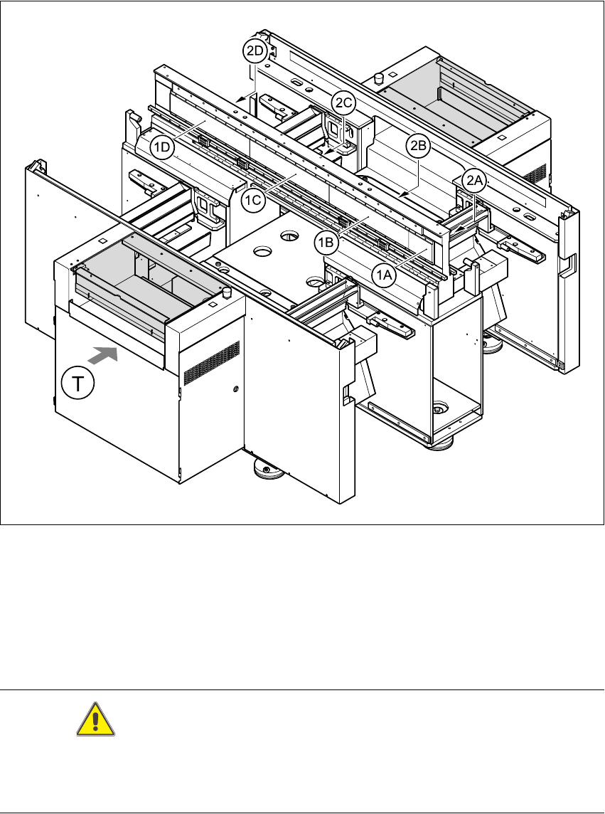
Fig. 4.12 - 1 Position of the permanent magnets of the Y-axis linear drives
Key
1A, 1B, 1C, 1DPermanent magnets for the Y-axis linear drive for gantries 1 and 4 4
2A, 2B, 2C, 2DPermanent magnets for the Y-axis linear drive for gantries 2 and 3 4
T Transport direction 4
CAUTION
When permanent magnets are placed on a magnetic surface (e.g. iron, nickel or steel), be ex-
tremely careful not to catch your hands or fingers between the surface and the permanent magnet.
If you do, you will not be able to lift the magnet from the surface on your own. 4

HS-60 Service Manual 4 Gantries
03/2003 US Issue 4.12 Replacing the linear motor - primary part (00333148-02)
125
Æ Remove the permanent magnets from the gantry concerned:
Gantry 1 or 2 4
Æ Loosen the four M6 x 12 hexagon socket-head screws on the permanent magnet (see
item 1A or 2A in Fig. 4.12 - 1
).
Æ Lift the permanent magnet and place it on a clean, non-magnetic surface (such as a plank
of wood).
Æ Loosen the 16 M6 x 12 hexagon socket-head screws on the permanent magnet (item 1B
or 2B in Fig. 4.12 - 1
).
Æ Set down the permanent magnet.
Gantry 3 or 4 4
Æ Loosen the 16 M6 x 12 hexagon socket-head screws on the permanent magnets (see
item 2C and 2D or 1C and 1D in Fig. 4.12 - 1
).
Æ Lift the permanent magnet and place it on a clean, non-magnetic surface (such as a plank
of wood).