Service Manual HS60.pdf - 第130页
4 G ant ri es HS- 6 0 S erv ice Ma nu al 4. 12 R epl ac in g t he line ar mo to r - pr ima r y pa rt ( 0033 31 48 -02 ) 03/ 200 3 US I ssue 128 4.12.5 In st alling th e primar y p art of th e linear motor Æ F it scotch t…
HS-60 Service Manual 4 Gantries
03/2003 US Issue 4.12 Replacing the linear motor - primary part (00333148-02)
127
Æ Loosen the nine M5 x 20 hexagon socket-head screws (item 3 in Fig. 4.12 - 3) and remove the
primary part laterally (item 2 in Fig. 4.12 - 3
).
Æ Make sure that the lock rails will not drop.
4
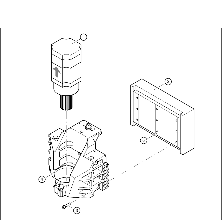
Fig. 4.12 - 3 Replacing the linear motor - primary part (2)
Key
(1) X-axis motor unit
(2) Linear motor - primary part
(3) 9 x M5 x 20 hexagon socket-head screws
(4) Motor bracket with press-fit connection (pneumatic system)
(5) Lockrail
4 Gantries HS-60 Service Manual
4.12 Replacing the linear motor - primary part (00333148-02) 03/2003 US Issue
128
4.12.5 Installing the primary part of the linear motor
Æ Fit scotch tape on the lower edge of the primary part of the linear motor to prevent the lockrails
from dropping.
Æ Push in the primary part from the side.
Æ Use the nine M5 x 20 hexagon socket-head screws (item 3 in Fig. 4.12 - 3) to fix the primary
part (item 2 in Fig. 4.12 - 3
) to the motor bracket (item 4 in Fig. 4.12 - 3).
Make sure that the primary part is aligned in parallel to the permanent magnet.
Æ Fit the X-axis motor unit as described in Section 4.11.4, page 121 onward.
Æ Fix all the cables with cable ties.
CAUTION 4
Make sure that the cables are firmly seated. Otherwise, the high acceleration forces may
cause the cable to slip out of position and shear through. 4
Æ Fit the permanent magnets (4 or 16 M6 x 12 hexagon socket-head screws).
Æ Fit the black cover strips on the cross-beam above the gantry concerned (3 M6 x 8 hexagon
socket-head screws).
4.12.6 Settings
Æ Use the belt tension measuring device to set the X-axis toothed belt tension to 53 Hz + 1/-3 Hz.
CAUTION 4
Do not overstretch the toothed belt when adjusting the belt tension. 4
Æ Secure the hexagon socket-head screw (item 2 in Fig. 4.11 - 1) with the locknut (item 8 in Fig.
4.11 - 1
).

Service Manual HS-60 5 Pneumatic Cutter and Empty-Tape Duct
03/2003 US Issue 5.1 Safety Instructions
129
5 Pneumatic Cutter and Empty-Tape
Duct
5.1 Safety Instructions
DANGER
The chapters "Operational Safety" in User Manual SIPLACE HS-60 and in this Service Manual
take precedence.
The machine SIPLACE HS-60 is powered by
219/380 V +/- 5% or
230/400 V +/- 5% or
239/415 V +/- 5% or
117/204 V +/- 5% or
133/230 V +/- 5%,
50/ 60 Hz line voltage
Portions of the system therefore conduct dangerous electricity. Inside the machine frame this is
true even while the master switch is turned off.
The machine has to be switched OFF and disconnected from the mains before you perform any
work in the area of the cutter.
In addition, the compressed air supply must be turned off at the main valve of the compressed air
unit in the machine frame and the compressed air lines must be bled by actuating the needle valve
on the compressed air unit.
Always secure the machine against unauthorized reactivation, as described in the User Manual,
chapter "Lock-Out and Tag-Out Procedure ...". 5