Service Manual HS60.pdf - 第133页
Se rv ice M a nu al HS- 6 0 5 P ne um at ic Cu tte r an d Em pt y-T ap e D uc t 03/ 200 3 U S Iss ue 5. 4 Over view of Mecha nica l Layo ut 131 5. 4 O ve rv i ew of M ec h an ic al L ayo u t 5 Fig. 5.4 . 1 Ov ervi ew o f…

5 Pneumatic Cutter and Empty-Tape Duct Service Manual HS-60
5.2 Parts 03/2003 US Issue
130
5.2 Parts
All spare parts are listed in the HS 60 spare parts catalogue, with their article numbers and dia-
grams. 5
NOTE:
These instructions are only valid for the version 04 pneumatic cutter and the associated version
03 empty-tape duct.
One of the new features of cutter version 04 is a tape deflector which is installed over the movable
blade (see Fig. 5.4.2 -> 6). 5
5.3 Tools, Expendable Materials, Documentation
– Thick protective gloves
– Set of socket wrenches, cross-slotted screwdriver size 4,
– Open-end wrench, width across flats 10; slotted screwdriver size 1
– Torque wrench, Diagonal cutter, Sliding caliper
– Feeler gauge 0.05mm; 1.0mm; 1.5mm, 2.0mm; 2.50mm
– Straight-edge (for check of tape deflector)
– Mounting plate, Item no.: 00312731-01
– 2 large parallel clamps (or mounting plate, see above)
– Flat, sturdy work bench to fasten the removed cutter (or mounting plate, see above)
– Loctite no. 234, Item no.: 00334892-01
– Molykote paste, Item no. 02100335-01, 250 g, (preferred) or
ISOFLEX TOPAS NCA 52, Item. no. 00330850-01, tube 50 g
– Water-insoluble, fine-tip marker and a dry and clean cloth
– Current edition of SIPLACE HS-60 spare parts catalogue and SIPLACE HS-60 detailed circuit
diagrams
– SITEST program and current SITEST operating manual
– Current edition of „HS-60 Adjustment Instructions“ documentation
Service Manual HS-60 5 Pneumatic Cutter and Empty-Tape Duct
03/2003 US Issue 5.4 Overview of Mechanical Layout
131
5.4 Overview of Mechanical Layout
5
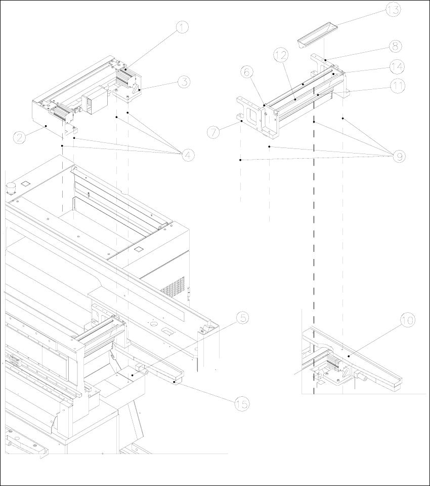
Fig. 5.4.1 Overview of Pneumatic Cutter Version 04 and Empty-Tape Duct Version 03

5 Pneumatic Cutter and Empty-Tape Duct Service Manual HS-60
5.4 Overview of Mechanical Layout 03/2003 US Issue
132
Key to Fig. 5.4.1
:
1. Pneumatic cutter HS-60
2. Retaining bracket for cutter, left
3. Retaining bracket for cutter, right
4. Fastening of the cutter,
2 socket hex head cap screws M6 x 25 each on left and right *)
Re-install any disks or plates that were previously removed.
5. Mounting surface for cutter on the machine frame
6. Empty-tape duct assembly
7. Side panel (left) of the empty-tape duct
8. Side panel (right) of the empty-tape duct
9. Fastening of "empty-tape duct assembly":
2 socket hex head cap screws M 4 x 16 each on left and right
10. Mounting surface for the "empty-tape duct assembly" on the machine frame
11. Baffle, inside
12. Baffle, outside
13. Reject box for nozzles
14. Reject box (profile)
15. Stop buffer assembly on left- and right-hand side of the machine frame,
Fastening: 2 socket hex head cap screws M8 each on left and right
*) Loosen these screws only when removing/installing the cutter (see Section 5.6.1.1
).