Service Manual HS60.pdf - 第134页
5 Pn eum ati c Cutt er and E mpty-T ape Du ct S er vic e Manu al HS- 60 5. 4 Ov e rvi ew of Mec ha ni ca l Lay out 03/ 200 3 US I ssue 132 Ke y to F ig. 5. 4. 1 : 1. Pneumat ic cutter HS-60 2. Retaining bracket f or cutt…
Service Manual HS-60 5 Pneumatic Cutter and Empty-Tape Duct
03/2003 US Issue 5.4 Overview of Mechanical Layout
131
5.4 Overview of Mechanical Layout
5
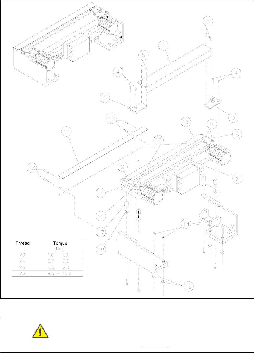
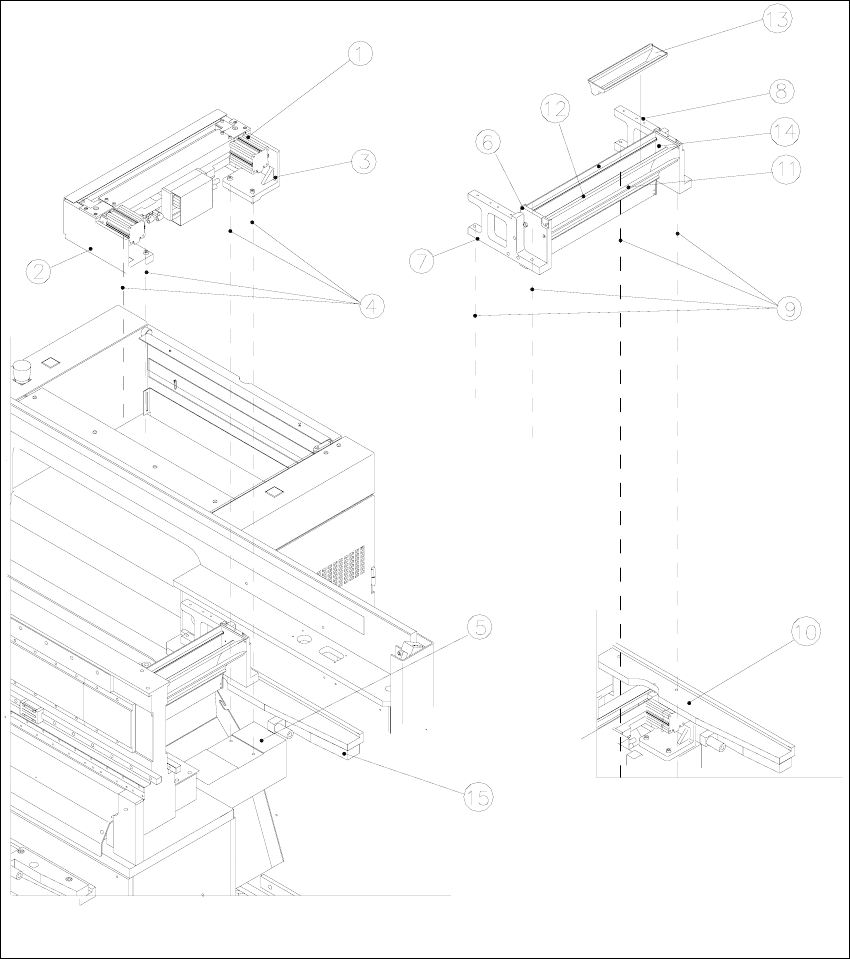
Fig. 5.4.1 Overview of Pneumatic Cutter Version 04 and Empty-Tape Duct Version 03

5 Pneumatic Cutter and Empty-Tape Duct Service Manual HS-60
5.4 Overview of Mechanical Layout 03/2003 US Issue
132
Key to Fig. 5.4.1
:
1. Pneumatic cutter HS-60
2. Retaining bracket for cutter, left
3. Retaining bracket for cutter, right
4. Fastening of the cutter,
2 socket hex head cap screws M6 x 25 each on left and right *)
Re-install any disks or plates that were previously removed.
5. Mounting surface for cutter on the machine frame
6. Empty-tape duct assembly
7. Side panel (left) of the empty-tape duct
8. Side panel (right) of the empty-tape duct
9. Fastening of "empty-tape duct assembly":
2 socket hex head cap screws M 4 x 16 each on left and right
10. Mounting surface for the "empty-tape duct assembly" on the machine frame
11. Baffle, inside
12. Baffle, outside
13. Reject box for nozzles
14. Reject box (profile)
15. Stop buffer assembly on left- and right-hand side of the machine frame,
Fastening: 2 socket hex head cap screws M8 each on left and right
*) Loosen these screws only when removing/installing the cutter (see Section 5.6.1.1
).