Service Manual HS60.pdf - 第135页
Se rv ice M a nu al HS- 6 0 5 P ne um at ic Cu tte r an d Em pt y-T ap e D uc t 03/ 200 3 U S Iss ue 5. 4 Over view of Mecha nica l Layo ut 133 Fig. 5.4 .2 Ov ervi ew: Remo ving and Inst all ing the Cov er Plate and the …

5 Pneumatic Cutter and Empty-Tape Duct Service Manual HS-60
5.4 Overview of Mechanical Layout 03/2003 US Issue
132
Key to Fig. 5.4.1
:
1. Pneumatic cutter HS-60
2. Retaining bracket for cutter, left
3. Retaining bracket for cutter, right
4. Fastening of the cutter,
2 socket hex head cap screws M6 x 25 each on left and right *)
Re-install any disks or plates that were previously removed.
5. Mounting surface for cutter on the machine frame
6. Empty-tape duct assembly
7. Side panel (left) of the empty-tape duct
8. Side panel (right) of the empty-tape duct
9. Fastening of "empty-tape duct assembly":
2 socket hex head cap screws M 4 x 16 each on left and right
10. Mounting surface for the "empty-tape duct assembly" on the machine frame
11. Baffle, inside
12. Baffle, outside
13. Reject box for nozzles
14. Reject box (profile)
15. Stop buffer assembly on left- and right-hand side of the machine frame,
Fastening: 2 socket hex head cap screws M8 each on left and right
*) Loosen these screws only when removing/installing the cutter (see Section 5.6.1.1
).

5 Pneumatic Cutter and Empty-Tape Duct Service Manual HS-60
5.4 Overview of Mechanical Layout 03/2003 US Issue
134
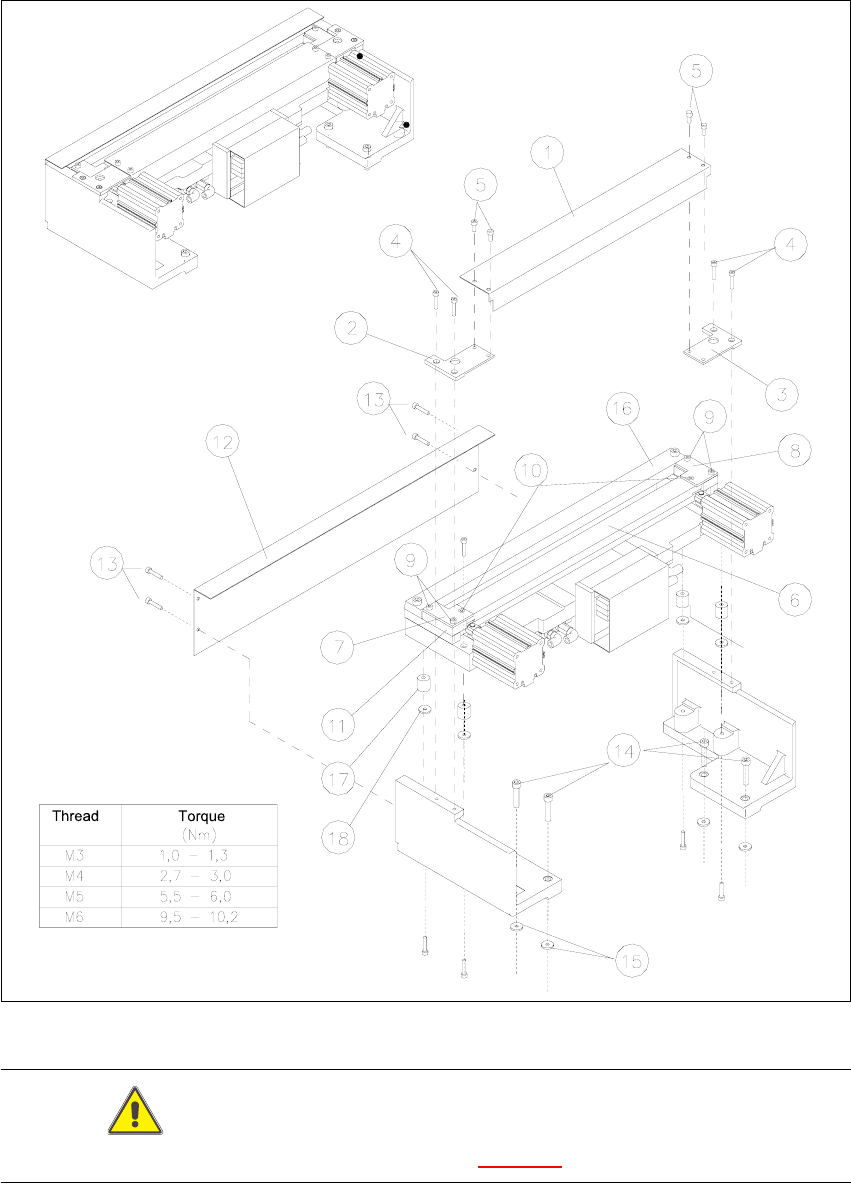
Key to Fig. 5.4.2
:
1. Cover plate
2. Cover plate holder, left
3. Cover plate holder, right
4. Screws to fasten the cover plate holder:
2 hexagon socket head screws M4 x 8 DIN 84 or 2 countersunk screws R M4 x 6 DIN 965 each
5. Screws to fasten the cover plate (incl. tape deflector) -> do not loosen!
6. Tape deflector (with moveable blade underneath)
7. Tape deflector holder, left
8. Tape deflector holder, right
9. Screws to fasten the tape deflector holders: 2 socket hex head cap screws M4 x 35 each on
the left and right
10. Screws to fasten the tape deflector: 1 countersunk screw each -> do not loosen!
11. Holddowns (at left and right) with spacers inserted underneath them
12. Deflector plate
13. Screws to fasten the deflector plate: 4 socket hex head cap screws M4 x 8
14. Screws to fasten the cutter on the machine frame
4 socket hex head cap screws M 6 x 25 *)
15. Any disks or plates installed underneath
16. Stationary blade
17. Rubber-metal vibration damper
18. Any disks and spring washers installed underneath
5
*) Loosen these screws only when removing/installing the cutter (see Section 5.6.1
). 5