Service Manual HS60.pdf - 第138页
5 Pn eum ati c Cutt er and E mpty-T ape Du ct S er vic e Manu al HS- 60 5.6 C h angi ng of parts 03/2 00 3 US I ss ue 136 5.6 Chang ing of p a rt s DANGER Strictly adhere to the inst ruct ions in t h e DANGER text in Se …
Service Manual HS-60 5 Pneumatic Cutter and Empty-Tape Duct
03/2003 US Issue 5.5 Diagrams of Pneumatic System and Functional Sequence
135
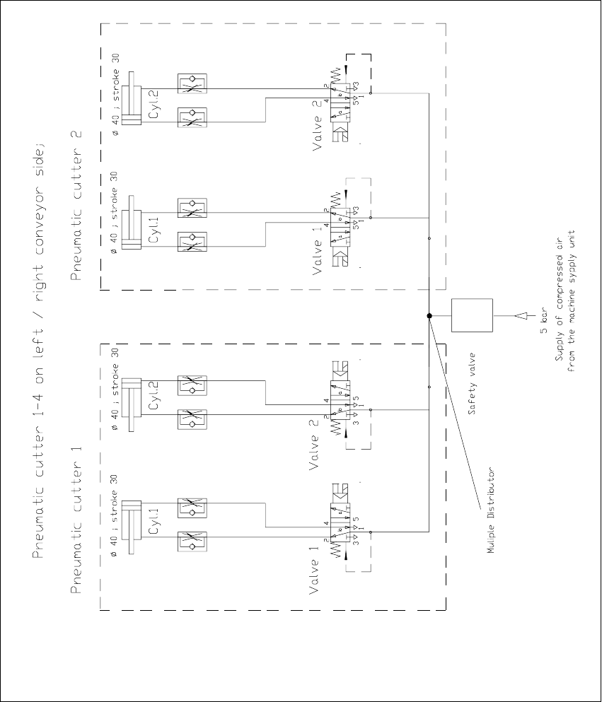
5.5 Diagrams of Pneumatic System and Functional
Sequence
Fig. 5.5.1 Diagram of Pneumatic System: Cutter per Conveyor Side
5 Pneumatic Cutter and Empty-Tape Duct Service Manual HS-60
5.6 Changing of parts 03/2003 US Issue
136
5.6 Changing of parts
DANGER
Strictly adhere to the instructions in the DANGER text in Section 5.1! 5
WARNING
Wear appropriate thick protective gloves whenever working near the blades / the tape deflector.
High risk of injury exists from stationary blade and movable blade and the tape deflector of the
cutter, even when the machine has been turned off.
Never reach into the pneumatic cutter from below or into the empty-tape duct from above, not
even to resolve a problem (e.g., when tape is jammed). 5
5.6.1 Exchanging the Pneumatic Cutter
WARNING
Wear appropriate thick protective gloves.
When removing the cutter, hold it only on the left and right, on the outside.
Never support the cutter on your body, e.g., on your knees or thighs.
Do not place your feet under the cutter.
You could injury yourself severely or at least damage your clothing.
Make certain that no one can injury themselves on the cutter after it has been dismantled. 5
Service Manual HS-60 5 Pneumatic Cutter and Empty-Tape Duct
03/2003 US Issue 5.6 Changing of parts
137
5.6.1.1 Removing the Cutter
Æ Turn the machine and then the compressed air ON.
Æ Disconnect the movable component changeover table from the machine and move it out of the
machine.
Æ Turn the machine OFF, disconnect the machine from the mains and turn off the flow of com-
pressed air at the compressed air unit. Actuate the needle valve on the compressed air unit to
bleed the compressed air lines (see DANGER text in Section 5.1
).
Æ Loosen the screws fastening the nozzle changer, lift it up somewhat and hold it in this position.
Æ Unplug the electrical cable and the pneumatic hose of the nozzle changer.
Æ Carefully put the nozzle changer down.
Æ Loosen the screws fastening the empty-tape duct assembly (see Fig. 5.4.1) and lift the duct
out of the machine.
WARNING
There is always a risk of injuring yourself with the cutting edge of the blades.
For this reason, the deflector plate, the cover and the protective sheet (see Fig. 5.4.2
) must be left
mounted in place. 5
Æ Take the cover off the cable pit (see Fig. 5.6.7 -> 5).
Æ Loosen the cutter’s compressed air connection (Y-socket union: see Fig. 5.6.3 -> 9) in the ca-
ble pit (see Fig. 5.6.7
-> 5).
Æ Remove the cover from the control board (see Fig. 5.6.5 -> 14).
Æ Unplug the plug-and-socket connection of the power supply and the drive on the control board
(see Fig. 5.6.5
-> 11, 10).
Æ Carefully undo the corresponding cable tie (left or right) on the outside of the control board box
(see Fig. 5.6.5
-> 15).
-> Do not damage the cables in this process.
Æ Place the cover back on the control board and on the cable pit.
Æ Remove the tape chute (it is only hooked in).
This makes the cutter easier to access for removal.
WARNING
The area under the cutter must be clear (e.g., do not place your feet under it either). 5