Service Manual HS60.pdf - 第141页
Se rv ice M a nu al HS- 6 0 5 P ne um at ic Cu tte r an d Em pt y-T ap e D uc t 03/ 200 3 U S Iss ue 5. 6 C h angi ng of pa rts 139 Æ Use a c able tie to fasten the cables running to the cable pit to the fixing ped estal…
5 Pneumatic Cutter and Empty-Tape Duct Service Manual HS-60
5.6 Changing of parts 03/2003 US Issue
138
Æ Undo the fasteners for the stop buffer assembly on left- and right-hand side of the machine
frame (two M8 socket hex head cap screws on each side, see Fig. 5.4.1
-> 15) under the
surface supporting for the component table.
Æ Loosen the screws fastening the cutter to the machine frame (2 screws, M6, on the left and
right retaining bracket, see Fig. 5.4.1
-> 2, 3 and 4):
– In exceptional cases, disks or plates may have been installed between the contact surface
of the cutter on the machine frame and the cutter itself.
-> Save these disks / plates and re-install them later.
Æ Securely hold the cutter tight at both ends.
Æ Pull the cutter out away from the contact surfaces (on the machine frame) towards the outside
of the machine (towards your body).
Æ Set the cutter down such that it does not pose a risk of injury to uninvolved personnel either.
Put it in its own crate / container immediately.
5.6.1.2 Installing the Cutter
Æ Make certain that the following warning signs are on the cover plate over the movable blade.
If not, install them (Item No.: see Section 5.2):
– Adhesive Label with text " Disconnect machine from mains voltage and....",
– Adhesive Label: Triangle warning symbol "Hand injury".
CAUTION
Tighten the screws to the correct torque -> see Table, Fig. 5.4.2. 5
Æ If there were disks or plates inserted between the contact surface of the cutter on the machine
frame and the cutter itself, re-install them now.
-> The cutter must be shimmed to the same height at all contact points however.
Æ In the reverse order to disassembly, place the new pneumatic cutter (Item no.: see Section 5.2)
on the contact surfaces of the machine frame and push it in to the threading position.
Æ To avoid dropping the cutter, insert all four M6 screws into the holes now:
Æ Pull the cutter as far as possible away from the PCB conveyor for the time being.
Æ Snug up the screws somewhat for the time being.
Æ Remove the cover from the control board of the new cutter.
Æ Make the plug-and-socket connections for the power supply and drive on the control board (al-
location: see Fig. 5.6.5
-> 11, 10).

Service Manual HS-60 5 Pneumatic Cutter and Empty-Tape Duct
03/2003 US Issue 5.6 Changing of parts
139
Æ Use a cable tie to fasten the cables running to the cable pit to the fixing pedestal on the control
board box (see Fig. 5.6.5
-> 15).
The strain on the cables / plug-and-socket connections must be relieved (see Fig. 5.6.7
-> 8).
Æ Remove the cover from the cable pit and make the compressed air connection to the machine
at the Y-plug-in coupling (see Fig. 5.6.3
-> 9).
Æ Place the cover back on the control board and the cable pit.
Æ Install the empty-tape duct assembly and check the entire length of the gap between the lead-
ing edge of the tape deflector and the "empty-tape baffle, inside", as described in Section 5.6.6
.
Æ If necessary, slide the cutter in the slots parallel to the direction of the PCB conveyor until you
reach the TARGET distance 1.0 to 1.5 mm (see Fig. 5.4.2
-> Detail).
Æ In this position tighten all 4 screws crosswise.
-> Tighten the screws to the correct torque -> see Table, Fig. 5.4.2
.
Æ Perform the appropriate “Final Steps” (see Section 5.6.8).
5 Pneumatic Cutter and Empty-Tape Duct Service Manual HS-60
5.6 Changing of parts 03/2003 US Issue
140
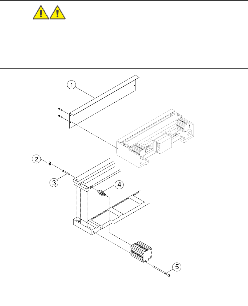
5.6.2 Replacing the articulated joint on the short-stroke cylinder (00348579-02)
WARNING
Wear thick protective gloves.
You might cut yourself on the blades and the tape deflector.
Never reach into the pneumatic cutter from below or into the empty-tape duct from above. 5
5
Fig. 5.6.1 Replacing the articulated joint on the short-stroke cylinder
Key to Fig. 5.6.1
(1) Deflector plate (4) Articulated joint
(2) Cover (5) Screws to fasten short-stroke cylinder
(3) Screws to fasten the moveable blade 5