Service Manual HS60.pdf - 第142页
5 Pn eum ati c Cutt er and E mpty-T ape Du ct S er vic e Manu al HS- 60 5.6 C h angi ng of parts 03/2 00 3 US I ss ue 140 5.6. 2 Replacing th e arti culated joint on t he sho rt-strok e cylind er (0034 8579-02) W ARNING …

Service Manual HS-60 5 Pneumatic Cutter and Empty-Tape Duct
03/2003 US Issue 5.6 Changing of parts
139
Æ Use a cable tie to fasten the cables running to the cable pit to the fixing pedestal on the control
board box (see Fig. 5.6.5
-> 15).
The strain on the cables / plug-and-socket connections must be relieved (see Fig. 5.6.7
-> 8).
Æ Remove the cover from the cable pit and make the compressed air connection to the machine
at the Y-plug-in coupling (see Fig. 5.6.3
-> 9).
Æ Place the cover back on the control board and the cable pit.
Æ Install the empty-tape duct assembly and check the entire length of the gap between the lead-
ing edge of the tape deflector and the "empty-tape baffle, inside", as described in Section 5.6.6
.
Æ If necessary, slide the cutter in the slots parallel to the direction of the PCB conveyor until you
reach the TARGET distance 1.0 to 1.5 mm (see Fig. 5.4.2
-> Detail).
Æ In this position tighten all 4 screws crosswise.
-> Tighten the screws to the correct torque -> see Table, Fig. 5.4.2
.
Æ Perform the appropriate “Final Steps” (see Section 5.6.8).
5 Pneumatic Cutter and Empty-Tape Duct Service Manual HS-60
5.6 Changing of parts 03/2003 US Issue
140
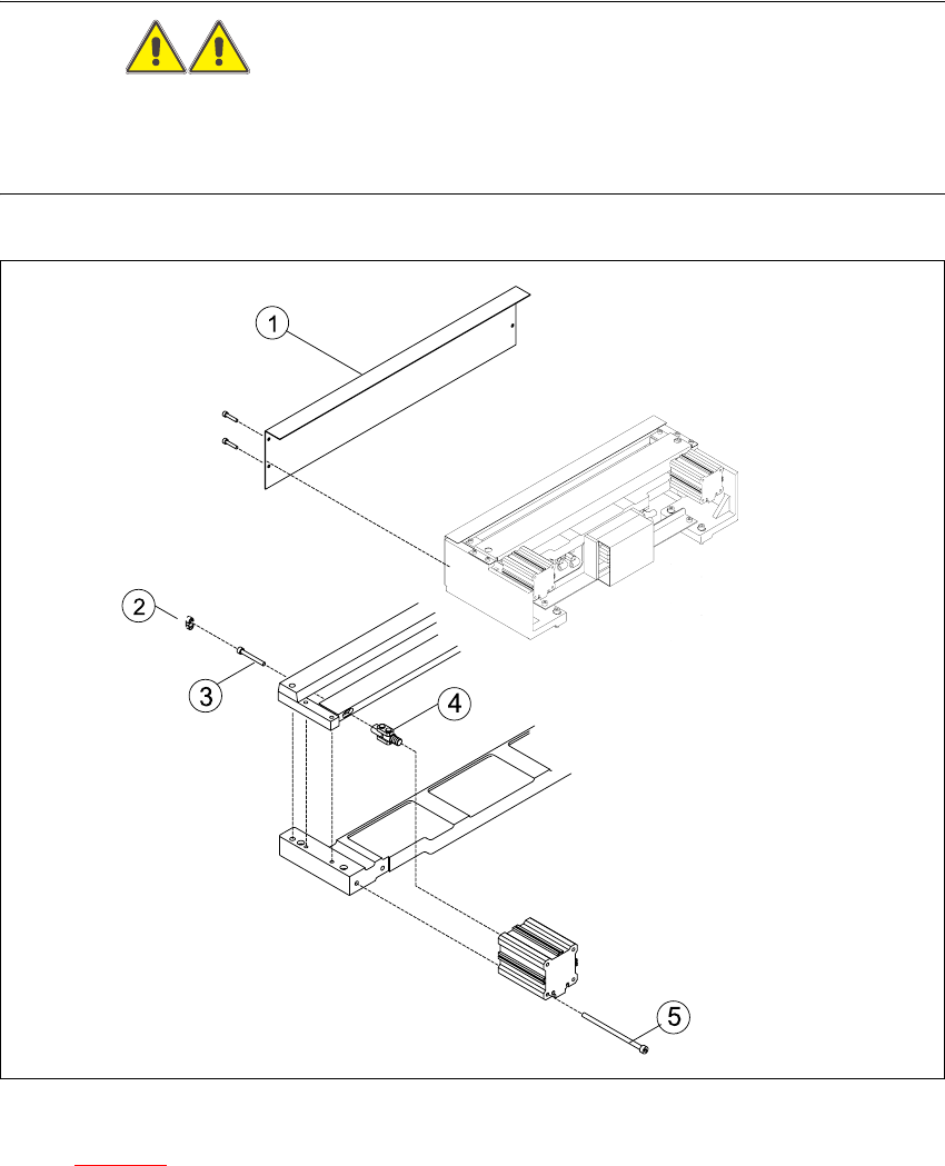
5.6.2 Replacing the articulated joint on the short-stroke cylinder (00348579-02)
WARNING
Wear thick protective gloves.
You might cut yourself on the blades and the tape deflector.
Never reach into the pneumatic cutter from below or into the empty-tape duct from above. 5
5
Fig. 5.6.1 Replacing the articulated joint on the short-stroke cylinder
Key to Fig. 5.6.1
(1) Deflector plate (4) Articulated joint
(2) Cover (5) Screws to fasten short-stroke cylinder
(3) Screws to fasten the moveable blade 5
Service Manual HS-60 5 Pneumatic Cutter and Empty-Tape Duct
03/2003 US Issue 5.6 Changing of parts
141
Æ Remove the cutter from the machine, as described in Section 5.6.1.
Æ Remove the deflector plate from the cutter.
Æ Loosen the screws holding the moveable blade.
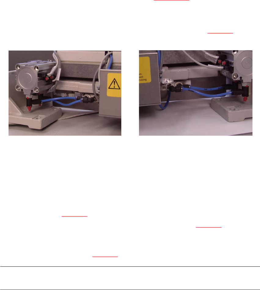
Æ Loosen the compressed air connections on the short-stroke cylinder (see Fig. 5.6.2.
5
Fig. 5.6.2 Compressed air connections
Æ Using a fine-tip, water-insoluble marker, accurately mark the specified position of the proximity
switch on the short-stroke cylinder.
Æ In addition, mark the allocation of the proximity switches to the short-stroke cylinder (position
front/back).
Æ Loosen the screws fastening the two inductive proximity switches to the short-stroke cylinder
(1 screw each: see Fig. 5.6.3
-> 4, 5).
Æ Loosen the screws fastening the short-stroke cylinder (2 screws: see Fig. 5.6.3 -> 5) and re-
move the cylinder, incl. the articulated joint screwed into it.
Æ Dismantle articulated joint from the cylinder by turning the open-end wrench (width across flats
10) on the surface indicated in Fig. 5.6.4
-> 3).
NOTE:
The threaded pin is secured with Loctite no. 243, so it takes somewhat more strength to loosen it.5