Service Manual HS60.pdf - 第143页
Se rv ice M a nu al HS- 6 0 5 P ne um at ic Cu tte r an d Em pt y-T ap e D uc t 03/ 200 3 U S Iss ue 5. 6 C h angi ng of pa rts 141 Æ Re move the cutter from the machine, as described in S e ction 5.6. 1 . Æ Re move the …
5 Pneumatic Cutter and Empty-Tape Duct Service Manual HS-60
5.6 Changing of parts 03/2003 US Issue
140
5.6.2 Replacing the articulated joint on the short-stroke cylinder (00348579-02)
WARNING
Wear thick protective gloves.
You might cut yourself on the blades and the tape deflector.
Never reach into the pneumatic cutter from below or into the empty-tape duct from above. 5
5
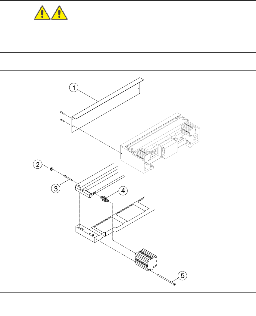
Fig. 5.6.1 Replacing the articulated joint on the short-stroke cylinder
Key to Fig. 5.6.1
(1) Deflector plate (4) Articulated joint
(2) Cover (5) Screws to fasten short-stroke cylinder
(3) Screws to fasten the moveable blade 5
Service Manual HS-60 5 Pneumatic Cutter and Empty-Tape Duct
03/2003 US Issue 5.6 Changing of parts
141
Æ Remove the cutter from the machine, as described in Section 5.6.1.
Æ Remove the deflector plate from the cutter.
Æ Loosen the screws holding the moveable blade.
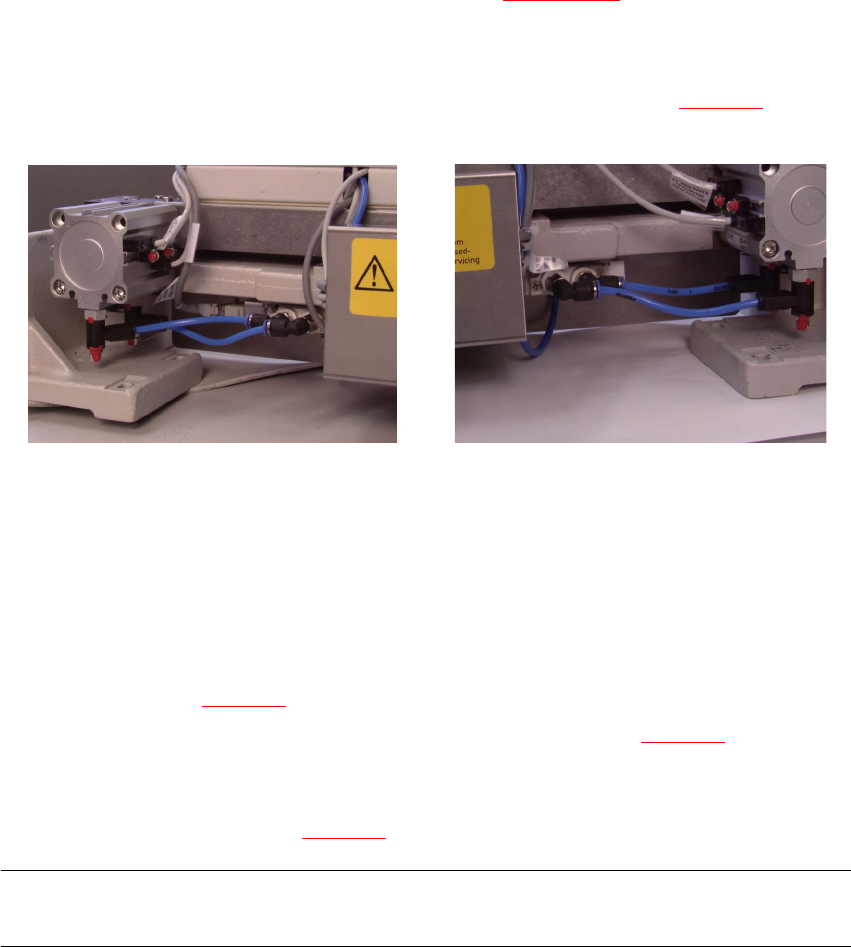
Æ Loosen the compressed air connections on the short-stroke cylinder (see Fig. 5.6.2.
5
Fig. 5.6.2 Compressed air connections
Æ Using a fine-tip, water-insoluble marker, accurately mark the specified position of the proximity
switch on the short-stroke cylinder.
Æ In addition, mark the allocation of the proximity switches to the short-stroke cylinder (position
front/back).
Æ Loosen the screws fastening the two inductive proximity switches to the short-stroke cylinder
(1 screw each: see Fig. 5.6.3
-> 4, 5).
Æ Loosen the screws fastening the short-stroke cylinder (2 screws: see Fig. 5.6.3 -> 5) and re-
move the cylinder, incl. the articulated joint screwed into it.
Æ Dismantle articulated joint from the cylinder by turning the open-end wrench (width across flats
10) on the surface indicated in Fig. 5.6.4
-> 3).
NOTE:
The threaded pin is secured with Loctite no. 243, so it takes somewhat more strength to loosen it.5
5 Pneumatic Cutter and Empty-Tape Duct Service Manual HS-60
5.6 Changing of parts 03/2003 US Issue
142
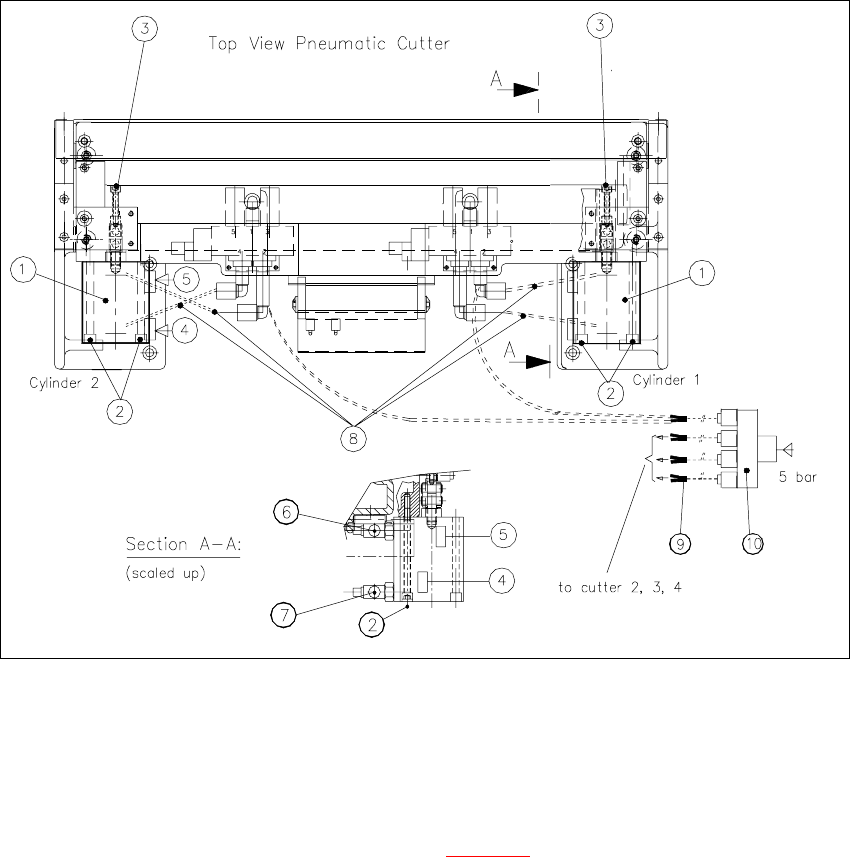
Fig. 5.6.3 Removing and Installing the Short-Stroke Cylinder
Key:
1. Short-stroke cylinders 1 and 2
2. Screws fastening the short-stroke cylinders: 2 socket hex head cap screws each, M5 x 65
3. Screws fastening the articulated joint (see also Fig. 5.6.4
)
4. Proximity switch (for position cylinder moved in). Fastener: 1 cross-slotted screw
5. Proximity switch (for position cylinder moved out). Fastener: 1 cross-slotted screw
6. One-way restrictor (for running cylinder out)
7. One-way restrictor (for running cylinder in)
8. Allocation of the compressed air connections, air hoses
9. Y-socket union (in the cable pit)
10. Multiple-Y-distributor on the safety valve (5 bar from compressed air unit)