Service Manual HS60.pdf - 第148页
5 Pn eum ati c Cutt er and E mpty-T ape Du ct S er vic e Manu al HS- 60 5.6 C h angi ng of parts 03/2 00 3 US I ss ue 146 10. CAN bus 11 . P o w e r s u p p l y 12. S pring-mounted elem ents to di sconne ct the control b…
Service Manual HS-60 5 Pneumatic Cutter and Empty-Tape Duct
03/2003 US Issue 5.6 Changing of parts
145
NOTE:
If the tapes are not cut correctly even though the switching points are set properly and the short-
stroke cylinder has been exchanged, complete with the one-way restrictor, the cause of the prob-
lem may be:
incorrect compressed air level/ leaking compressed air connection or Y-socket union, blade in
poor condition, faulty solenoid valve or a break in the drive circuit of the solenoid valve. 5
Æ Perform the appropriate "Final Steps" (see Section 5.6.8).
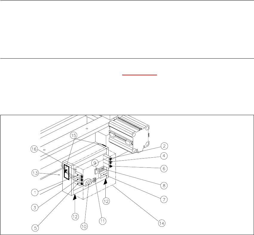
5.6.3 Exchanging the Control Unit
Fig. 5.6.5 Exchanging the Control Unit, Allocation of the Plug-and-Socket Connections
Key:
1. Drive of solenoid valve for cylinder 2 (left)
2. Drive of solenoid valve for cylinder 1 (right)
3. to the proximity switch on cylinder 2, FRONT
4. to the proximity switch on cylinder 1, FRONT
5. to the proximity switch on cylinder 2, BACK
6. to the proximity switch on cylinder 1, BACK
7. Cutter power supply (only busy on S-23 and F5)
8. Drive of cutter (only busy on S-23 and F5)
9. Service plug (to be used exclusively by Siemens)
5 Pneumatic Cutter and Empty-Tape Duct Service Manual HS-60
5.6 Changing of parts 03/2003 US Issue
146
10. CAN bus
11. Power supply
12. Spring-mounted elements to disconnect the control board box
13. Support bar
14. Cover
15. Fixing pedestal adhesive type (LH and RH) with cable tie
Relieve tensile stress on cable/plug-and-socket connections.
16.Coding plug
WARNING
You might cut yourself on the blades and the tape deflector.
Never reach into the pneumatic cutter from below or into the empty-tape duct from above. 5
The cutter remains installed in the machine. 5
Æ Turn the machine and then the compressed air ON.
Æ Disconnect the movable component changeover table from the machine and move it out of the
machine.
Æ Turn the machine OFF.
Æ Remove the cover from the control board.
Æ Carefully undo the cable ties (left and right) on the outside of the control board box (see
Fig. 5.6.7
-> 10).
-> Do not damage the cables in this process.
Æ Mark the allocation of all plug-and-socket connectors and disconnect all plug-and-socket con-
nections on the control unit (see Fig. 5.6.5
).
Æ Disconnect the control unit (box) from the support bar by pushing both of the spring-mounted
elements away from the ba.
Æ Install the new control unit (Item no.: see Section 5.2), correctly rotated and positioned, on the
bar and engage the unit.
Æ Mount an adhesive fixing pedestal for cable ties on the outside LH and RH side of the control
board box (see Fig. 5.6.6
for location).
Service Manual HS-60 5 Pneumatic Cutter and Empty-Tape Duct
03/2003 US Issue 5.6 Changing of parts
147
5
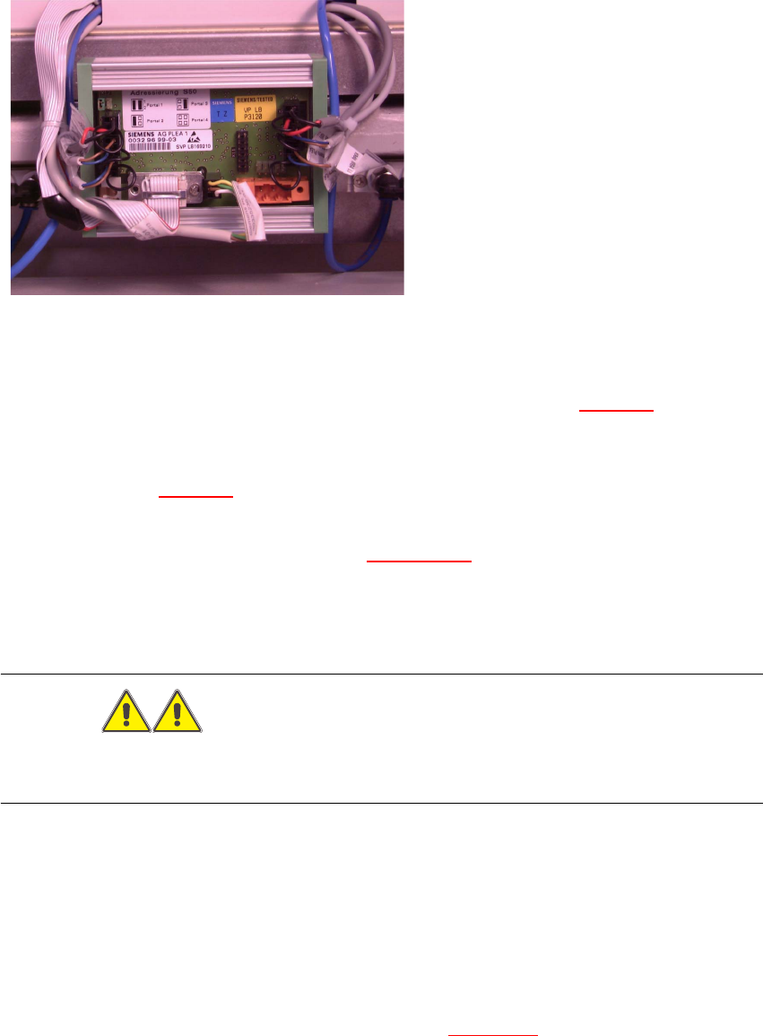
Fig. 5.6.6 Control Unit
5
Æ Restore all plug-and-socket connections in the correct allocation (see Fig. 5.6.5).
Æ Use a cable tie to fasten the cables running to the LH and RH side of the cable pit to the fixing
pedestal (on control board box). The strain on the cables/plug-and-socket connections must
be relieved (see Fig. 5.6.7
-> 8).
Æ Place the cover back on the control board.
Æ Perform the appropriate “Final Steps” (see Section 5.6.8).
5.6.4 Exchanging the Solenoid Valve on Left or Right (and/or Cable)
WARNING
You might cut yourself on the blades and the tape deflector.
Never reach into the pneumatic cutter from below or into the empty-tape duct from above. 5
The cutter remains installed in the machine. 5
Æ Turn the machine and then the compressed air ON.
Æ Disconnect the movable component changeover table from the machine and move it out of the
machine.
Æ Turn the machine OFF, disconnect the machine from the mains and turn off the flow of com-
pressed air at the compressed air. Actuate the needle valve on the compressed air unit to
bleed the compressed air lines (see DANGER text in Section 5.1
).