Service Manual HS60.pdf - 第149页
Se rv ice M a nu al HS- 6 0 5 P ne um at ic Cu tte r an d Em pt y-T ap e D uc t 03/ 200 3 U S Iss ue 5. 6 C h angi ng of pa rts 147 5 Fig. 5.6 .6 C ont rol Un it 5 Æ Re store all plug-and-socket connections in the correc…
5 Pneumatic Cutter and Empty-Tape Duct Service Manual HS-60
5.6 Changing of parts 03/2003 US Issue
146
10. CAN bus
11. Power supply
12. Spring-mounted elements to disconnect the control board box
13. Support bar
14. Cover
15. Fixing pedestal adhesive type (LH and RH) with cable tie
Relieve tensile stress on cable/plug-and-socket connections.
16.Coding plug
WARNING
You might cut yourself on the blades and the tape deflector.
Never reach into the pneumatic cutter from below or into the empty-tape duct from above. 5
The cutter remains installed in the machine. 5
Æ Turn the machine and then the compressed air ON.
Æ Disconnect the movable component changeover table from the machine and move it out of the
machine.
Æ Turn the machine OFF.
Æ Remove the cover from the control board.
Æ Carefully undo the cable ties (left and right) on the outside of the control board box (see
Fig. 5.6.7
-> 10).
-> Do not damage the cables in this process.
Æ Mark the allocation of all plug-and-socket connectors and disconnect all plug-and-socket con-
nections on the control unit (see Fig. 5.6.5
).
Æ Disconnect the control unit (box) from the support bar by pushing both of the spring-mounted
elements away from the ba.
Æ Install the new control unit (Item no.: see Section 5.2), correctly rotated and positioned, on the
bar and engage the unit.
Æ Mount an adhesive fixing pedestal for cable ties on the outside LH and RH side of the control
board box (see Fig. 5.6.6
for location).
Service Manual HS-60 5 Pneumatic Cutter and Empty-Tape Duct
03/2003 US Issue 5.6 Changing of parts
147
5
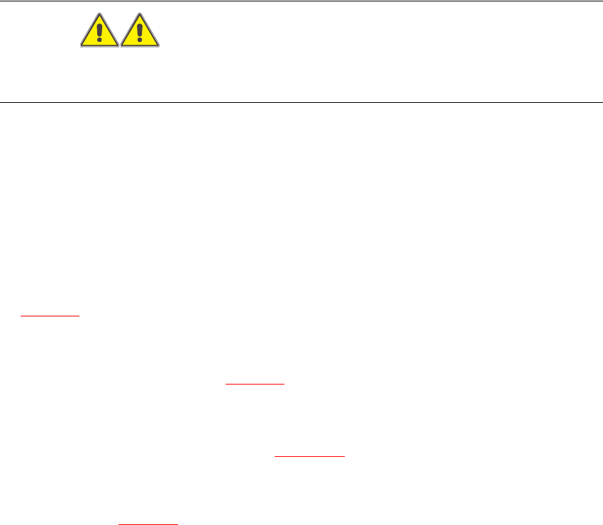
Fig. 5.6.6 Control Unit
5
Æ Restore all plug-and-socket connections in the correct allocation (see Fig. 5.6.5).
Æ Use a cable tie to fasten the cables running to the LH and RH side of the cable pit to the fixing
pedestal (on control board box). The strain on the cables/plug-and-socket connections must
be relieved (see Fig. 5.6.7
-> 8).
Æ Place the cover back on the control board.
Æ Perform the appropriate “Final Steps” (see Section 5.6.8).
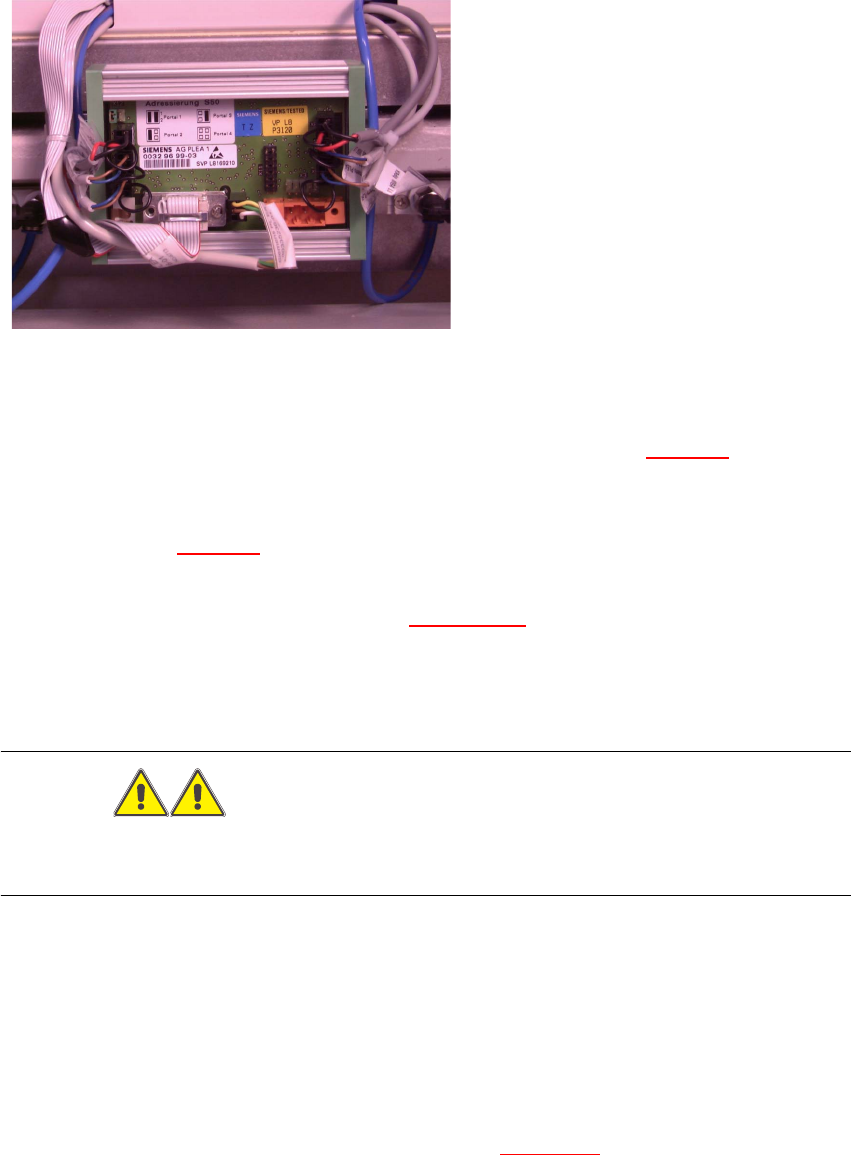
5.6.4 Exchanging the Solenoid Valve on Left or Right (and/or Cable)
WARNING
You might cut yourself on the blades and the tape deflector.
Never reach into the pneumatic cutter from below or into the empty-tape duct from above. 5
The cutter remains installed in the machine. 5
Æ Turn the machine and then the compressed air ON.
Æ Disconnect the movable component changeover table from the machine and move it out of the
machine.
Æ Turn the machine OFF, disconnect the machine from the mains and turn off the flow of com-
pressed air at the compressed air. Actuate the needle valve on the compressed air unit to
bleed the compressed air lines (see DANGER text in Section 5.1
).

5 Pneumatic Cutter and Empty-Tape Duct Service Manual HS-60
5.6 Changing of parts 03/2003 US Issue
148
Key to Fig. 5.6.7
(right):
1. Solenoid valve for cylinder 1, incl. mounting strap
2. Solenoid valve for cylinder 2, incl. mounting strap
3. to the plug-and-socket connection of the appropriate solenoid valve
4. Screws for fastening the solenoid valve: 2 socket hex head cap screws each, M3 x 6
5. Cover of the cable pit
6. Compressed air hoses for cylinder 1
7. Compressed air hoses for cylinder 2
8. No strain on cable/plug-and-socket connections
9. Cover
10. Fixing pedestal, adhesive type, with cable tie (LH and RH)
11. Plug-and-socket connection on the solenoid valve