Service Manual HS60.pdf - 第151页
Se rv ice M a nu al HS- 6 0 5 P ne um at ic Cu tte r an d Em pt y-T ap e D uc t 03/ 200 3 U S Iss ue 5. 6 C h angi ng of pa rts 149 Fig. 5.6 . 7 Exc hangi ng t he Sol enoi d Valv e

5 Pneumatic Cutter and Empty-Tape Duct Service Manual HS-60
5.6 Changing of parts 03/2003 US Issue
148
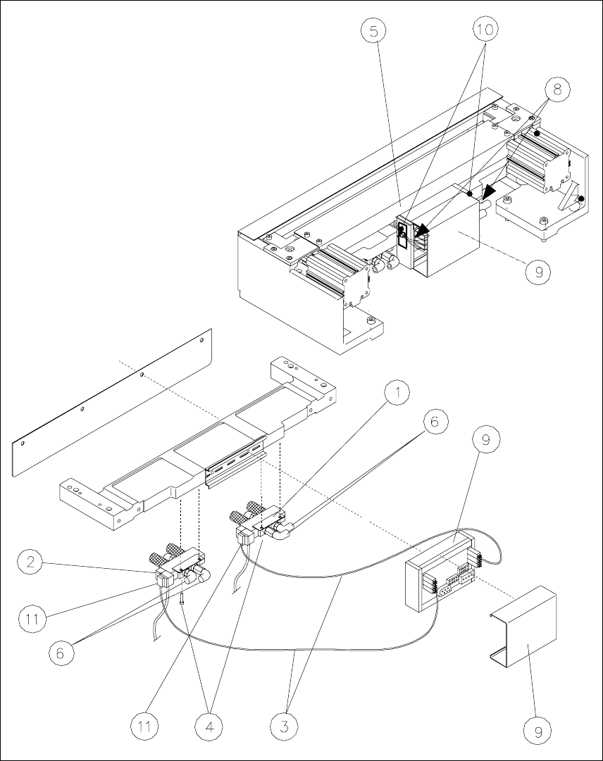
Key to Fig. 5.6.7
(right):
1. Solenoid valve for cylinder 1, incl. mounting strap
2. Solenoid valve for cylinder 2, incl. mounting strap
3. to the plug-and-socket connection of the appropriate solenoid valve
4. Screws for fastening the solenoid valve: 2 socket hex head cap screws each, M3 x 6
5. Cover of the cable pit
6. Compressed air hoses for cylinder 1
7. Compressed air hoses for cylinder 2
8. No strain on cable/plug-and-socket connections
9. Cover
10. Fixing pedestal, adhesive type, with cable tie (LH and RH)
11. Plug-and-socket connection on the solenoid valve
Service Manual HS-60 5 Pneumatic Cutter and Empty-Tape Duct
03/2003 US Issue 5.6 Changing of parts
149
Fig. 5.6.7 Exchanging the Solenoid Valve

5 Pneumatic Cutter and Empty-Tape Duct Service Manual HS-60
5.6 Changing of parts 03/2003 US Issue
150
If the cable of the solenoid valve is faulty:
Æ Carefully undo the corresponding cable tie (left or right) on the outside of the control board
box (see Fig. 5.6.7
-> 10).
-> Do not damage the cables in this process.
Æ Remove the cover from the control board (see Fig. 5.6.7 -> 9).
Æ Unplug the plug-and-socket connection of the cable "Control board for tape cutter - valve"
of the appropriate solenoid valve on the control board (see Fig. 5.6.5
-> 1, 2).
Æ Loosen the plug-and-socket connection of the cable "Control board for tape cutter - valve"
of the appropriate solenoid valve (see Fig. 5.6.5
).
Æ Take the cover off the cable pit (see Fig. 5.6.7 -> 5).
Æ Remove the cable and run the new cable "Control board for tape cutter - valve" (Item no.:
see Section 5.2
). Push the excess lengths of cable into the cable pit.
Æ Make the plug-and-socket connection on the board (see Fig. 5.6.5) and on the solenoid
valve with correct allocation (see Fig. 5.6.7
).
Æ Place the cover back on the control board (see Fig. 5.6.7 -> 9).
Æ Install the cover on the cable pit (see Fig. 5.6.7 -> 5).
Æ Use a cable tie to fasten the cables running to LH and/or RH side of the cable pit to the fixing
pedestal (on control board box).
The strain on the cable / plug-and-socket connections must be relieved (see Fig. 5.6.7
-> 8).
Æ Perform the appropriate “Final Steps” (see Section 5.6.8).
If the solenoid valve is faulty:
Æ Undo the 2 compressed air connections on the one-way restrictors at the faulty solenoid
valve (see Fig. 5.6.7
-> 1, 2, 6).
Æ Unplug the plug-and-socket connection of the cable "Control board tape cutter - valve"
on the faulty solenoid valve (see Fig. 5.6.7
-> 11).
Æ Undo the screws fastening the faulty solenoid valve (2 M3 screws: see Fig. 5.6.7 -> 4) and
remove the solenoid valve.
Æ Mount the new solenoid valve (Item no.: see Section 5.2) in the correct position, as shown
in Fig. 5.6.7. Make the plug-and-socket connection at the solenoid valve:
-> Tighten the screws to the correct torque -> see Table, Fig. 5.4.2
.
-> The strain on the cable must be relieved (see Fig. 5.6.7
-> 8).