Service Manual HS60.pdf - 第154页
5 Pn eum ati c Cutt er and E mpty-T ape Du ct S er vic e Manu al HS- 60 5.6 C h angi ng of parts 03/2 00 3 US I ss ue 152 5 5 5. 6. 5. 2 Ins t al ling th e P roxi mit y Sw it ch Æ Ins tall the new proximity switch (Item …

Service Manual HS-60 5 Pneumatic Cutter and Empty-Tape Duct
03/2003 US Issue 5.6 Changing of parts
151
Æ Mount the short-stroke cylinder compressed air connections to the one-way restrictors on
the solenoid valve with the correct allocation (see Fig. 5.6.3
-> 6, 7, 8).
Æ Perform the appropriate “Final Steps” (see Section 5.6.8).
5.6.5 Exchanging the Inductive Proximity Switch
5.6.5.1 Removing the Proximity Switch
The cutter remains installed in the machine.
Æ Turn the machine and then the compressed air ON.
Æ Disconnect the movable component changeover table from the machine and move it out of the
machine.
Æ Turn the machine OFF, disconnect the machine from the mains and turn off the flow of com-
pressed air at the compressed air. Actuate the needle valve on the compressed air unit to
bleed the compressed air lines (see DANGER text in Section 5.1
).
Æ Remove the cover from the control board (see Fig. 5.6.5 -> 14).
Æ Carefully undo the corresponding cable tie (left or right) on the outside of the control board box
(see Fig. 5.6.5
-> 10).
-> Do not damage the cables in the process.
Æ Using a fine-tip permanent marker, precisely mark on the short-stroke cylinder the specified
position of the proximity switch that is to be exchanged.
Æ Disengage the plug-and-socket connection of the faulty proximity switch on the control board
(allocation: see Fig. 5.6.5
).
If you loosen more than one of the plug-and-socket connection simultaneously, mark the allo-
cation.
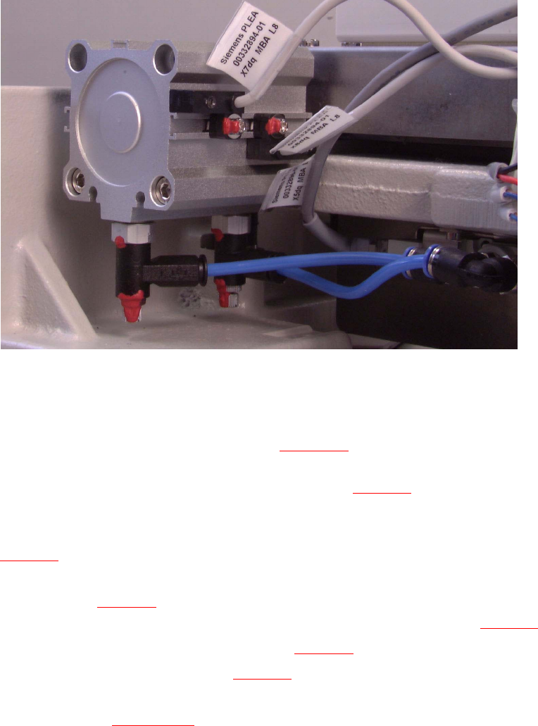
Æ Take the cover off the cable pit (see Fig. 5.6.7 -> 5).
Æ Undo the screw fastening the proximity switch to the short-stroke cylinder (1 screw: see pic-
ture) and remove the proximity switch including the cable.
5 Pneumatic Cutter and Empty-Tape Duct Service Manual HS-60
5.6 Changing of parts 03/2003 US Issue
152
5
5
5.6.5.2 Installing the Proximity Switch
Æ Install the new proximity switch (Item no.: see Section 5.2) precisely in the position you marked
on the short-stroke cylinder with the permanent marker.
-> Tighten the screws to the correct torque -> see Table, Fig. 5.4.2
.
Æ Lay the cable in the cable pit and make the plug-and-socket connection to the proximity switch
on the control board with correct allocation to the proximity switch left/right and front/back (see
Fig. 5.6.5
) -> Push the excess lengths of cable into the cable pit.
Æ Use a cable tie to fasten the cables running to the cable pit to the fixing pedestal on the control
board box (see Fig. 5.6.7
-> 10).
The strain on the cables / plug-and-socket connections must be relieved (see Fig. 5.6.7
-> 8).
Æ Place the cover back on the control board (see Fig. 5.6.7 -> 9).
Æ Install the cover on the cable pit (see Fig. 5.6.7 -> 5).
Æ Perform the "Final Steps" including the substep "Load the SITEST program and initiate the cut-
ting strokes" (see Section 5.6.8
).
Service Manual HS-60 5 Pneumatic Cutter and Empty-Tape Duct
03/2003 US Issue 5.6 Changing of parts
153
5.6.6 Exchanging the Empty-Tape Duct Assembly
WARNING
You might cut yourself on the blades and the tape deflector.
Never reach into the pneumatic cutter from below or into the empty-tape duct from above. 5
Æ Turn the machine and then the flow of compressed air ON.
Æ Disconnect the movable component changeover table from the machine and move it out of the
machine.
Æ Turn the machine OFF, disconnect the machine from the mains and turn off the flow of com-
pressed air at the compressed air. Actuate the needle valve on the compressed air unit to
bleed the compressed air lines (see DANGER text in Section 5.1
).
Æ Loosen the screws fastening the nozzle changer, lift it up somewhat and hold it in this position.
Æ Unplug the electrical cable and the pneumatic hose of the nozzle changer.
Æ Carefully put the nozzle changer down.
Æ Loosen the screws fastening the empty-tape duct assembly (see Fig. 5.4.1 -> 11, 9) and lift the
duct out of the machine.
Æ If you only want to exchange the faulty baffle inside/outside and/or the reject box, proceed as
indicated in Section 5.6.7
.
Æ Screw the "empty-tape duct assembly" (Item no.: see Section 5.2) on the machine base (2
screws each on left and right, M4 x 16).
-> Tighten the screws to the correct torque -> see Table in Fig. 5.4.2
.
WARNING
The following check can only be conducted from the bottom of the cutter after it has been installed
in the machine. Wear thick protective gloves; there is a risk of injury from the blades and the edge
of the tape deflector. 5
NOTE:
For the adjustments it is the best, if a second person is available 5
Æ With the feeler gauge, check:
The distance between the empty-tape baffle and the leading edge of the tape deflector must
again be within the TARGET distance 1.0 to 1.5 mm over the entire length (see Fig. 5.4.2
->
Detail).