Service Manual HS60.pdf - 第155页
Se rv ice M a nu al HS- 6 0 5 P ne um at ic Cu tte r an d Em pt y-T ap e D uc t 03/ 200 3 U S Iss ue 5. 6 C h angi ng of pa rts 153 5.6. 6 Excha nging the Empty-T ape Duct Assembl y W ARNING Y ou might cut y o urself on …
5 Pneumatic Cutter and Empty-Tape Duct Service Manual HS-60
5.6 Changing of parts 03/2003 US Issue
152
5
5
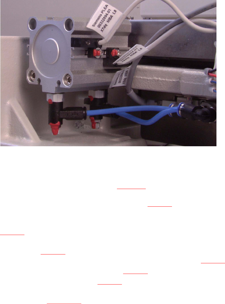
5.6.5.2 Installing the Proximity Switch
Æ Install the new proximity switch (Item no.: see Section 5.2) precisely in the position you marked
on the short-stroke cylinder with the permanent marker.
-> Tighten the screws to the correct torque -> see Table, Fig. 5.4.2
.
Æ Lay the cable in the cable pit and make the plug-and-socket connection to the proximity switch
on the control board with correct allocation to the proximity switch left/right and front/back (see
Fig. 5.6.5
) -> Push the excess lengths of cable into the cable pit.
Æ Use a cable tie to fasten the cables running to the cable pit to the fixing pedestal on the control
board box (see Fig. 5.6.7
-> 10).
The strain on the cables / plug-and-socket connections must be relieved (see Fig. 5.6.7
-> 8).
Æ Place the cover back on the control board (see Fig. 5.6.7 -> 9).
Æ Install the cover on the cable pit (see Fig. 5.6.7 -> 5).
Æ Perform the "Final Steps" including the substep "Load the SITEST program and initiate the cut-
ting strokes" (see Section 5.6.8
).
Service Manual HS-60 5 Pneumatic Cutter and Empty-Tape Duct
03/2003 US Issue 5.6 Changing of parts
153
5.6.6 Exchanging the Empty-Tape Duct Assembly
WARNING
You might cut yourself on the blades and the tape deflector.
Never reach into the pneumatic cutter from below or into the empty-tape duct from above. 5
Æ Turn the machine and then the flow of compressed air ON.
Æ Disconnect the movable component changeover table from the machine and move it out of the
machine.
Æ Turn the machine OFF, disconnect the machine from the mains and turn off the flow of com-
pressed air at the compressed air. Actuate the needle valve on the compressed air unit to
bleed the compressed air lines (see DANGER text in Section 5.1
).
Æ Loosen the screws fastening the nozzle changer, lift it up somewhat and hold it in this position.
Æ Unplug the electrical cable and the pneumatic hose of the nozzle changer.
Æ Carefully put the nozzle changer down.
Æ Loosen the screws fastening the empty-tape duct assembly (see Fig. 5.4.1 -> 11, 9) and lift the
duct out of the machine.
Æ If you only want to exchange the faulty baffle inside/outside and/or the reject box, proceed as
indicated in Section 5.6.7
.
Æ Screw the "empty-tape duct assembly" (Item no.: see Section 5.2) on the machine base (2
screws each on left and right, M4 x 16).
-> Tighten the screws to the correct torque -> see Table in Fig. 5.4.2
.
WARNING
The following check can only be conducted from the bottom of the cutter after it has been installed
in the machine. Wear thick protective gloves; there is a risk of injury from the blades and the edge
of the tape deflector. 5
NOTE:
For the adjustments it is the best, if a second person is available 5
Æ With the feeler gauge, check:
The distance between the empty-tape baffle and the leading edge of the tape deflector must
again be within the TARGET distance 1.0 to 1.5 mm over the entire length (see Fig. 5.4.2
->
Detail).
5 Pneumatic Cutter and Empty-Tape Duct Service Manual HS-60
5.6 Changing of parts 03/2003 US Issue
154
If the gap is not OK.
Æ Loosen the screws holding the empty-tape duct once again and correct the position of the
duct in the holes.
Æ If this is not enough, you may assume that the cutter was already not in the optimal position
before the empty-tape duct was exchanged:
In this case, correct the position of the cutter in the slots of the retaining brackets in the man-
ner described for the installation of the cutter in Section 5.6.1.2
.
5.6.7 Exchanging Baffles and / or Reject Box (Profile)
The "empty-tape duct assembly" has already been removed, as described in Section 5.6.6.
Æ Undo the self-tapping M4 screws fastening the baffle or reject box that you want to dismantle
(see detail in Fig. 5.4.2
, 13 to 18).
Æ Insert the new baffle inside/outside and /or the new reject box (Item no.: see Section 5.2) and
fasten it with the self-tapping screws (see Fig. 5.4.2
-> 13 to 18).
Æ Install the empty-tape duct assembly and check the gap between the leading edge of the tape
deflector and the “empty-tape baffle, inside", as described in Section 5.6.6
.
Æ Perform the appropriate “Final Steps” (see Section 5.6.8).
5.6.8 Final Steps
CAUTION
Tighten the screws to the correct torque -> see Table, Fig. 5.4.2. 5
Æ Make certain that each of the cables running out of the left and right of the control board box
is again fastened to the fixing pedestal with cable tie.
The strain on the cables / plug-and-socket connections must be relieved (Fig. 5.6.7
-> 8).
Æ Check the gap between the leading edge of the tape deflector and the "empty-tape baffle, in-
side", as described in Section 5.6.6
.
Æ Where applicable, mount the tape chute into the machine.
Æ From below mount the stop buffer assembly on the machine frame (two M8 socket hex head
cap screws on left and right).
Æ If the nozzle changer is removed, stop the nozzle changer over the installation position and
and make the electrical and pneumatic connections.
Æ Mount the nozzle changer.
Æ Turn the compressed air back on at the main switch on the compressed air unit.