Service Manual HS60.pdf - 第163页
Se rv ice M a nu al HS-6 0 6 Mo du la r P CB con ve y or s yst em 03/ 200 3 U S Iss ue 6.6 Ov erv ie w 161 6.6 Overvie w 6.6. 1 Singl e conveyor system The HS-60 singl e con veyor system consi st s of an input conveyor ,…
6 Modular PCB conveyor system Service Manual HS-60
6.5 Function 03/2003 US Issue
160
– The placement rate no longer depends on the thickness of the PCB.
– The recognition of PCB fiducials is optimized.
The constant distance between the PCB upper edge and the PCB camera means that the PCB
camera is always focussed clearly on the PCB surface. The PCB fiducial are always optimally
displayed on the CCD chip of the PCB camera.
PCB conveyor systems are configured within the machine so that, with the 12-segment col-
lect&place head, placement can be performed on components to a maximum height of 6 mm and,
with the 6-segment collect&place head (S-27 HM), on components to a max. of 8.5 mm.
The transport height can be set to allow the machines to be integrated into lines with 830, 900,
930 or 950 mm transport height. Communication between the PCB conveyors of the individual
machines is possible via either a SIEMENS or SMEMA interface.
PCB transport is monitored and controlled by light barriers, consisting of both a transmitter and
receiver module:
– Once a PCB reaches the placement area, it is recognized by a light barrier and the speed of
the conveyor belt is reduced.
– Approximately 100 ms later, the front edge of the slowly progressing PCB is detected by a laser
beam and the PCB is stopped and clamped in placed from underneath.
Service Manual HS-60 6 Modular PCB conveyor system
03/2003 US Issue 6.6 Overview
161
6.6 Overview
6.6.1 Single conveyor system
The HS-60 single conveyor system consists of an input conveyor, two placement areas, the inter-
mediate conveyor and the output conveyor. The S-27 HM has only one placement area. In this
case, the single conveyor system consists of input conveyor, placement area and output con-
veyor. Each conveyor system has automatic width adjustment and a lifting table for clamping the
PCB in place.
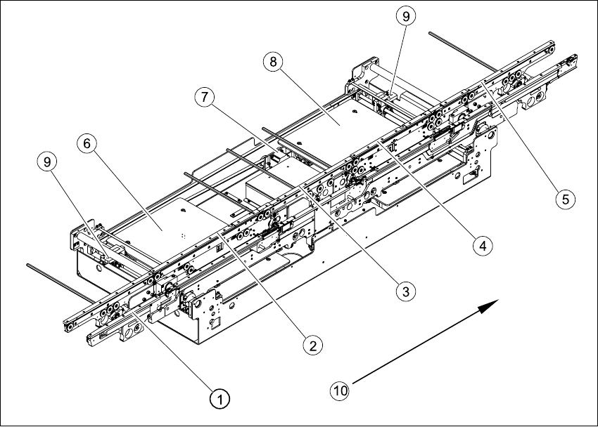
Fig. 6.6.1 Overview - modular conveyor system (single conveyor)
Key
(1) Input conveyor (6) Lifting table placement area 1
(2) Placement area 1 (7) Width adjustment drive unit
(3) Intermediate conveyor (8) Lifting table placement area 2
(4) Placement area 2 (9) Width adjustment for adjustment units 1
and 2
(5) Output conveyor (10) Direction of transport
6 Modular PCB conveyor system Service Manual HS-60
6.6 Overview 03/2003 US Issue
162
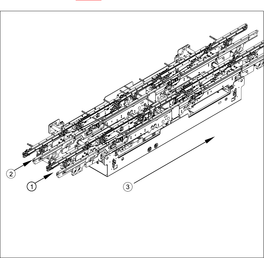
6.6.2 Dual conveyor system
The dual conveyor system has two conveyor tracks. In the standard model, the fixed conveyor
side is on the right side of each track.
As in the case of the single conveyor system, the dual conveyor system consists of an input con-
veyor, two placement areas (HS-60 only), the intermediate conveyor (HS-60 only) and the output
conveyor. The dual conveyor system has automatic width adjustment and a lifting table to clamp
the PCB in place. See also Fig. 6.6.1
)
Fig. 6.6.2 Overview - modular conveyor system (dual conveyor)
Key
(1) Conveyor track 1 (3) Direction of transport
(2) Conveyor track 2