Service Manual HS60.pdf - 第165页
Se rv ice M a nu al HS-6 0 6 Mo du la r P CB con ve y or s yst em 03/ 2003 US Issu e 6.7 Repl acin g the comp lete dr ive uni t (0 0359 284- 02) 163 6.7 Repla cing the c ompl ete drive u nit (0035 9284-02) Fig. 6.7 . 3 R…
6 Modular PCB conveyor system Service Manual HS-60
6.6 Overview 03/2003 US Issue
162
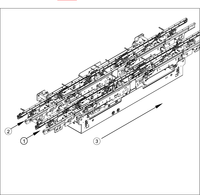
6.6.2 Dual conveyor system
The dual conveyor system has two conveyor tracks. In the standard model, the fixed conveyor
side is on the right side of each track.
As in the case of the single conveyor system, the dual conveyor system consists of an input con-
veyor, two placement areas (HS-60 only), the intermediate conveyor (HS-60 only) and the output
conveyor. The dual conveyor system has automatic width adjustment and a lifting table to clamp
the PCB in place. See also Fig. 6.6.1
)
Fig. 6.6.2 Overview - modular conveyor system (dual conveyor)
Key
(1) Conveyor track 1 (3) Direction of transport
(2) Conveyor track 2
Service Manual HS-60 6 Modular PCB conveyor system
03/2003 US Issue 6.7 Replacing the complete drive unit (00359284-02)
163
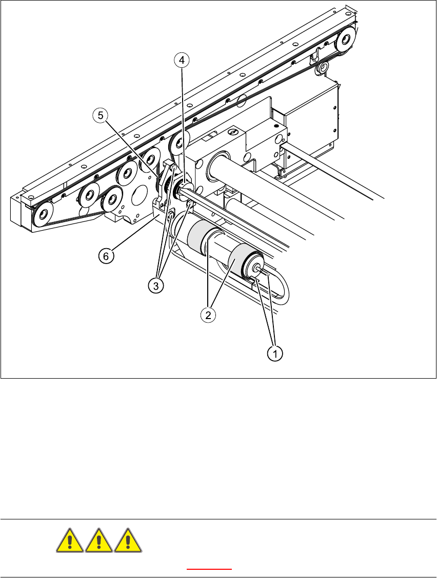
6.7 Replacing the complete drive unit (00359284-02)
Fig. 6.7.3 Replacing the complete drive unit (00359284-02)
Key
DANGER
Please observe the safety instructions in Chapter 2.
(1) Cable connections (4) Clamping ring
(2) Heat-shrinkable sleeves (5) Conveyor toothed belt
(3) Fastening screws (6) Motor mount

6 Modular PCB conveyor system Service Manual HS-60
6.7 Replacing the complete drive unit (00359284-02) 03/2003 US Issue
164
CAUTION
The toothed belts must not be stretched or kinked!
6.7.1 Parts
– 00359284-02 drive unit
6.7.2 Removal
The DC geared motors, including the motor mounts of all 5 conveyor areas, are of like construc-
tion. Please bear in mind the following differences during assembly and disassembly.
– The motor mount in installed at an angle (tilted), according to the requirements of the installa-
tion site.
– Depending upon the installation position, the motor mount will either be fixed with a clamping
ring or a circlip.
Conduct the procedures for replacement as described below:
Æ For disassembly at PCB conveyor 2 (dual conveyor):
Move conveyor 1 only far enough apart, that the outside of the fixed conveyor assembly of
conveyor 2 and the screws fastening the motor are still accessible.
Æ For disassembly at the single conveyor or conveyor 1 of the dual conveyor:
Move the conveyor to maximum width.
Æ Move the Y-gantries into the area outside the PCB conveyor.
Æ Turn the machine off at the main switch and disconnect the machine from the mains voltage.
Æ Make sure the machine has been properly secured to prevent it being switched on again during
servicing.
Æ Mark the polarity of the cable connections (+ / -) - important for the direction of rotation!
Æ Disconnect the cable shoes from the motor terminals.
Æ The heat-shrinkable sleeves which hold the connecting cable in place must be stripped off the
circumference of the DC geared motor.
Æ Remove the clamping ring (or circlip).
Æ Remove the 3 screws holding the motor mount in place.
Æ Carefully dismantle the motor mount and gently weave out the conveyor toothed belt.