Service Manual HS60.pdf - 第166页
6 Modu lar PCB conv eyor syste m Ser vic e Manu al HS- 60 6. 7 R ep laci ng th e c omp le te dri v e u ni t (0 03 592 84 -02 ) 0 3/2 00 3 US I ss ue 164 CAUTION The t oothed belts m ust n ot be stre tch ed or ki nke d! 6…
Service Manual HS-60 6 Modular PCB conveyor system
03/2003 US Issue 6.7 Replacing the complete drive unit (00359284-02)
163
6.7 Replacing the complete drive unit (00359284-02)
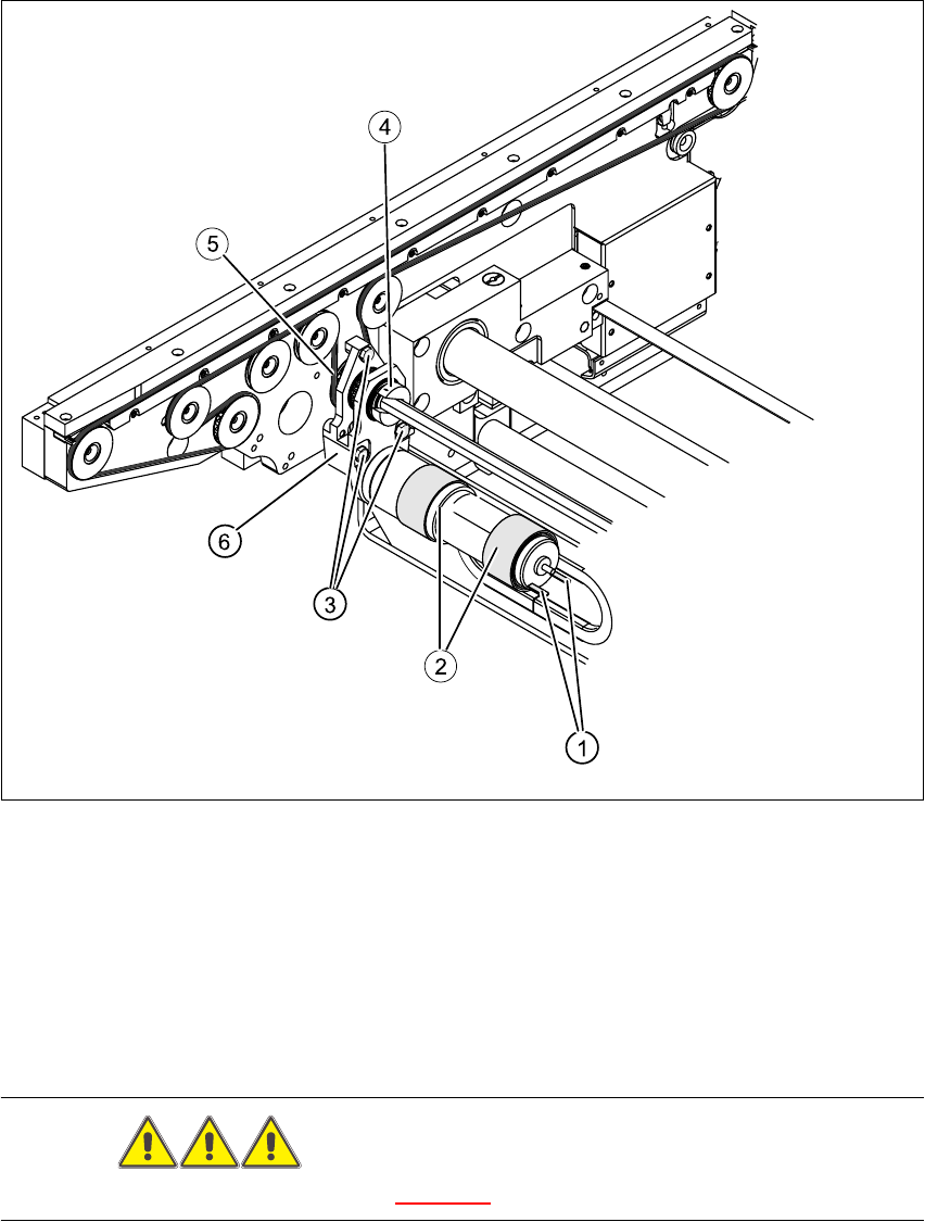
Fig. 6.7.3 Replacing the complete drive unit (00359284-02)
Key
DANGER
Please observe the safety instructions in Chapter 2.
(1) Cable connections (4) Clamping ring
(2) Heat-shrinkable sleeves (5) Conveyor toothed belt
(3) Fastening screws (6) Motor mount

6 Modular PCB conveyor system Service Manual HS-60
6.7 Replacing the complete drive unit (00359284-02) 03/2003 US Issue
164
CAUTION
The toothed belts must not be stretched or kinked!
6.7.1 Parts
– 00359284-02 drive unit
6.7.2 Removal
The DC geared motors, including the motor mounts of all 5 conveyor areas, are of like construc-
tion. Please bear in mind the following differences during assembly and disassembly.
– The motor mount in installed at an angle (tilted), according to the requirements of the installa-
tion site.
– Depending upon the installation position, the motor mount will either be fixed with a clamping
ring or a circlip.
Conduct the procedures for replacement as described below:
Æ For disassembly at PCB conveyor 2 (dual conveyor):
Move conveyor 1 only far enough apart, that the outside of the fixed conveyor assembly of
conveyor 2 and the screws fastening the motor are still accessible.
Æ For disassembly at the single conveyor or conveyor 1 of the dual conveyor:
Move the conveyor to maximum width.
Æ Move the Y-gantries into the area outside the PCB conveyor.
Æ Turn the machine off at the main switch and disconnect the machine from the mains voltage.
Æ Make sure the machine has been properly secured to prevent it being switched on again during
servicing.
Æ Mark the polarity of the cable connections (+ / -) - important for the direction of rotation!
Æ Disconnect the cable shoes from the motor terminals.
Æ The heat-shrinkable sleeves which hold the connecting cable in place must be stripped off the
circumference of the DC geared motor.
Æ Remove the clamping ring (or circlip).
Æ Remove the 3 screws holding the motor mount in place.
Æ Carefully dismantle the motor mount and gently weave out the conveyor toothed belt.

Service Manual HS-60 6 Modular PCB conveyor system
03/2003 US Issue 6.7 Replacing the complete drive unit (00359284-02)
165
NOTE:
The way in which the conveyor toothed belt is run around the belt guide depends upon the trans-
port area concerned. Please observe this belt guidance during assembly.
NOTE:
If you have discovered a break in the motor cable during a continuity check, the motor cable must
be woven out as far as the conversion board of the conveyor side (see circuit diagrams of the
same name) and unplugged at the corresponding point. This may be somewhat complicated de-
pending on the routing of cables inside the machine base.
You may wish to contact Siemens Dematic AG SMD Service regarding this work.
6.7.3 Installation
Æ Install the new drive unit in the reverse order.
Æ Please check: the entire width of the conveyor toothed belt must engage at all synchronizing
disks and be run around the belt guide.
Æ Where applicable, install the guide rails on the conveyor component. Do not tighten this com-
pletely as it still needs to be adjusted.
Æ If guide rails have been loosened or remounted, you will need to readjust the alignment of the
guide rails (see Section 6.15
).
Æ Perform the „Final steps including function check“ (see Section 6.18).
NOTE:
After the new drive unit has been installed, you must make certain that the direction of rotation
and the conveyor speed (motor voltage) are correct.
After reconnecting the geared motor, you will only need to check the direction of rotation.