Service Manual HS60.pdf - 第172页
6 Modu lar PCB conv eyor syste m Ser vic e Manu al HS- 60 6.9 R epl acin g the toot hed b elt of t he re leva nt P CB conv eyor dr ive ( 0035 5553 -01 ) 03 /20 03 US Is sue 170 DANGER Please observe the safety instructio…
Service Manual HS-60 6 Modular PCB conveyor system
03/2003 US Issue 6.9 Replacing the toothed belt of the relevant PCB conveyor drive (00355553-01)
169
6.9 Replacing the toothed belt of the relevant PCB con-
veyor drive (00355553-01)
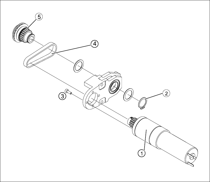
Fig. 6.9.5 Replacing the toothed belt of the relevant PCB conveyor drive
Key
(1) DC geared motor (4) Toothed belt
(2) Circlip (5) Synchronizing disk
(3) 4 x fastening screws
6 Modular PCB conveyor system Service Manual HS-60
6.9 Replacing the toothed belt of the relevant PCB conveyor drive (00355553-01) 03/2003 US Issue
170
DANGER
Please observe the safety instructions in Chapter 2.
CAUTION
The toothed belt must not be stretched or kinked!
6.9.1 Removal
The DC geared motors, including the motor mounts of all 5 conveyor areas, are of like construc-
tion. Please bear in mind the following differences during assembly and disassembly.
– The motor mount in installed at an angle (tilted), according to the requirements of the installa-
tion site.
– Depending upon the installation position, the motor mount will either be fixed with a clamping
ring or a circlip.
Conduct the procedures for replacement of all toothed belts as described below:
Æ Remove the complete drive unit, as described in Section 6.7
Æ Working from the fixed exterior side of the conveyor, undo the screws fastening the DC geared
motor
(4 hexagonal socket-head screws, see Fig. 6.8.4
).
Æ Tilt the DC geared motor with its synchronized disk a little, so that the small toothed belt of the
drive comes free of the synchronizing disk and then pull the motor out.
Please note:
– The toothed belt on the motor pinion must not be stretched or kinked.
– The synchronizing disk on the motor shaft must be moved out in such a manner that is does
not get caught in the toothed belt.
Æ Remove the circlip and shim, see Fig. 6.9.5.
Æ Use a small rubber mallet to carefully knock the synchronizing disk out of the motor mount.
Æ Remove the toothed belt from the mount.
Service Manual HS-60 6 Modular PCB conveyor system
03/2003 US Issue 6.9 Replacing the toothed belt of the relevant PCB conveyor drive (00355553-01)
171
6.9.2 Installation
CAUTION
The new toothed belt must not be stretched or kinked! during the following procedure
Æ Insert the new toothed belt into the motor mount and place the belt around the synchronizing
disk of the geared motor.
Æ Place the toothed belt around the synchronizing disk of the conveyor toothed belt and insert
the synchronizing disk in its mount.
Æ Use a rubber mallet to carefully knock the synchronizing disk into position.
Æ Loosely fasten the DC geared motor with the 4 M3 hexagonal socket-head screws The entire
width of the toothed belt must engage at the top and bottom synchronizing disk.
Æ Install the complete motor unit as described in Section 6.7.3.
Æ Perform the „Final steps including function check“ (see Section 6.18).
NOTE:
After the new drive unit has been installed, you must make certain that the direction of rotation and
the conveyor speed (motor voltage) are correct.
After reconnecting the geared motor, you will only need to check the direction of rotation.