Service Manual HS60.pdf - 第176页
6 Modu lar PCB conv eyor syste m Ser vic e Manu al HS- 60 6. 10 R epl ac in g t he con ve yor t oot hed be lt (00 36 48 47- 0 1) 03/ 200 3 US I ssue 174 6.10.2 Replacing th e conveyo r toothe d belt Fig . 6 .10. 7 Re pla…
Service Manual HS-60 6 Modular PCB conveyor system
03/2003 US Issue 6.10 Replacing the conveyor toothed belt (00364847-01)
173
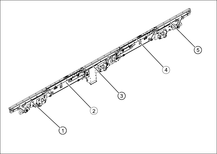
Fig. 6.10.6 Overview of conveyor toothed belt (example with mounting))
Key
(1) Input conveyor (4) Placement area 2 (HS-60 only)
(2) Placement area 1 (5) Output conveyor
(3) Intermediate conveyor (HS-60 only)
6 Modular PCB conveyor system Service Manual HS-60
6.10 Replacing the conveyor toothed belt (00364847-01) 03/2003 US Issue
174
6.10.2 Replacing the conveyor toothed belt
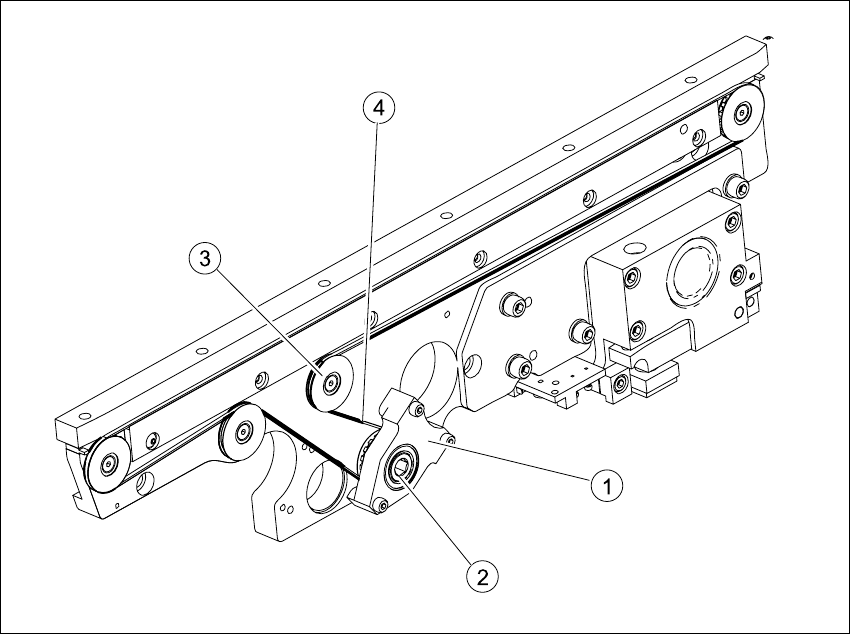
Fig. 6.10.7 Replacing the conveyor tooted belt (example with mounting)
Key
6.10.2.1 Removal
The way in which the conveyor toothed belt is run around the deflection pulley depends upon the
transport area concerned. Please observe this belt guidance during assembly and disassembly.
Please also observe the following differences during assembly and disassembly work.
– The drive unit is installed at an angle (tilted), according to the requirements of the installation
site.
– Depending upon the installation position, the drive unit will either be fixed with a clamping ring
or a circlip.
– The mount is installed on one side of the conveyor, while the DC geared motor is mounted on
the other side.
(1) Motor mount (3) Deflection pulley with slot (not visible)
(2) Clamping ring or circlip (4) Conveyor toothed belt

Service Manual HS-60 6 Modular PCB conveyor system
03/2003 US Issue 6.10 Replacing the conveyor toothed belt (00364847-01)
175
Conduct the procedures for replacement as described below:
Æ Move the PCB conveyor to the position which gives you best access to the conveyor belt.
Æ Move the Y-gantries into the area outside the PCB conveyor.
Æ Turn the machine off at the main switch and disconnect the machine from the mains voltage.
Æ Make sure the machine has been properly secured to prevent it being switched on again during
servicing.
Æ If the drive unit is installed, remove it as described in Section 6.7.
Æ If the mount is installed, remove the clamping ring or circlip on the mount and the 3 screws
fastening the mount in place (see Fig. 6.10.7
).
Æ Loosen the deflection pulley with the slot and relieve the tension on the belt.
Æ Carefully extract the mount or the drive unit, while also gently weaving out the conveyor
toothed belt.
6.10.2.2 Installation
CAUTION
The new toothed belt must not be stretched or kinked!
Æ Feed the new toothed belt into the drive unit and weave around the deflection pulleys.
Æ Insert the drive unit with the conveyor toothed belt and fasten the mount or the drive unit.
Please refer to Section 6.7.3
for installation instructions for the drive unit.
Æ Adjust the belt tension as described in Section 6.10.3.