Service Manual HS60.pdf - 第181页
Se rv ice M a nu al HS-6 0 6 Mo du la r P CB con ve y or s yst em 03/ 200 3 U S Iss ue 6.11 Li ftin g table 179 6.1 1.2 Repla cing th e lif ting ta b le (0035 8653-04) ) DANGER Plea se observe the saf ety inst ructions i…
6 Modular PCB conveyor system Service Manual HS-60
6.11 Lifting table 03/2003 US Issue
178
6.11 Lifting table
DANGER
Please observe the safety instructions in Chapter 2.
6.11.1 Function
Depending on the model (single or dual conveyor), each placement area has one or two indepen-
dently functioning lifting tables in use. The lifting table is driven indirectly via a pneumatic cylinder,
with magnetic valve control. Different PCB thicknesses are automatically compensated. Move-
ment along the Z-axis is measured at four points on the lifting table plate. A position measuring
system determines the lifting path. The top position of the lifting table is recognized by the position
measuring system and a Piezo force transducer (see also Section 6.11.6
). The bottom position of
the lifting table is identified by the position measuring system and the end position proximity switch
on the pneumatic cylinder.
NOTE:
The standard space under the PCB is 40 mm. The previously used PCB supports are no longer
suitable.
Service Manual HS-60 6 Modular PCB conveyor system
03/2003 US Issue 6.11 Lifting table
179
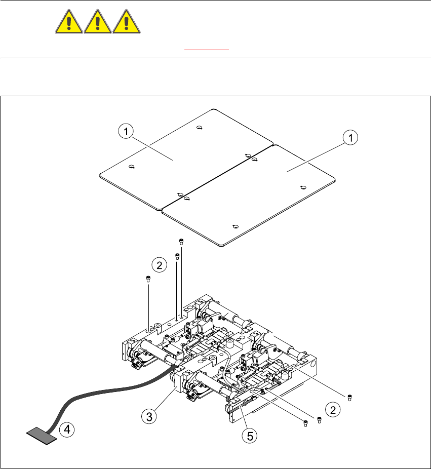
6.11.2 Replacing the lifting table (00358653-04))
DANGER
Please observe the safety instructions in Chapter 2.
Fig. 6.11.9 Replacing the lifting table
Key
(1) Lifting table plate (4) Connection cable for lifting table unit
(2) Fastening screws for the lifting table unit (5) Pneumatic connections
(3) Lifting table unit

6 Modular PCB conveyor system Service Manual HS-60
6.11 Lifting table 03/2003 US Issue
180
6.11.2.1 Parts
– 00358653-04 Lifting table unit for single conveyors
– 00358654-04 Lifting table unit for dual conveyors
6.11.2.2 Removal
Æ For single conveyor systems, move the PCB conveyor to its maximum position, giving you the
best access to the lifting table unit.
NOTE:
For dual conveyor systems, you will need to move the conveyor track 1 to the minimum position
and then move the fixed side of the conveyor track 2 mechanically.
Æ Move the Y-gantries into the area outside the PCB conveyor.
Æ Turn the machine off at the main switch and disconnect the machine from the mains voltage.
Æ Make sure the machine has been properly secured to prevent it being switched on again during
servicing.
Æ For dual conveyor systems, you will need to mechanically release and then move the fixed side
of conveyor track 2, to enable you to lift the lifting table out of the machine.
Æ To do this, undo the screw fastening the brake in place (see Section 6.12). Slightly loosen (do
not unscrew fully) the grub screw in the fastening screw.
Æ Remove the fastening screw. Take care not to lose the spring inside.
Æ Move the side of the conveyor on the fixed side so that you can lift the lifting table out of the
machine.
Æ Undo the screws fastening the lifting table plate and remove the lifting table from the lifting ta-
ble unit.
Æ Undo the 6 screws fastening the lifting table unit.
Æ Remove the cover of the conveyor conversion board and unplug the lifting table connection
cable.
Æ Remove the pneumatic connection from the vacuum valve.
Æ Carefully lift the lifting table out of the locating pins.