Service Manual HS60.pdf - 第185页
Se rv ice M a nu al HS-6 0 6 Mo du la r P CB con ve y or s yst em 03/ 200 3 U S Iss ue 6.11 Li ftin g table 183 6.1 1 .3.1 Re mov al Æ M ove the PCB conve yor to the position which allows you bes t access to the l i ft i…
6 Modular PCB conveyor system Service Manual HS-60
6.11 Lifting table 03/2003 US Issue
182
6.11.3 Replacing and adjusting the silencer (00358684-05)
The silencer moves the lifting table gently upwards. It prevents the PCBs being clamped in with
too much impact.
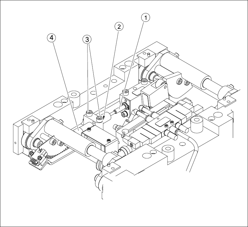
Fig. 6.11.10 Replacing and adjusting the silencer
Key
(1) Actuator (3) Fastening screws
(2) Locknut (4) Handle

Service Manual HS-60 6 Modular PCB conveyor system
03/2003 US Issue 6.11 Lifting table
183
6.11.3.1 Removal
Æ Move the PCB conveyor to the position which allows you best access to the lifting table unit.
Æ Move the Y-gantries into the area outside the PCB conveyor.
Æ Turn the machine off at the main switch and disconnect the machine from the mains voltage.
Æ Make sure the machine has been properly secured to prevent it being switched on again during
servicing.
Æ Undo the screws fastening the lifting table plate and remove the lifting table plate from the lifting
table unit.See also Fig. 6.11.9
Æ Undo the two screws fastening the silencer.
Æ Undo the locknut. Take the silencer by its handle and twist it out of the mounting block.
6.11.3.2 Installation and adjustment
Æ Insert and twist the new silencer into the mounting block until the slide just touches the actua-
tor, so that the lifting table can be gently moved upwards.
Æ Secure this position with the locknut.
Æ Install the lifting table.
Æ Check whether the silencer has been fixed onto the mounting block with the locknut and that
the silencer slide has a gap of approx. 0.1 - 0.2 mm to the actuator (untriggered mode). In this
basic position, the lifting table should move gently upwards and activate the clamping sensor
in the conveyor side.
Æ If this is not the case, loosen the locknut and turn the silencer approx. one rotation into the
mounting block.
Æ Start the SITEST program and move the lifting table upwards.
Æ The lifting table must move gently upwards and activate the clamping sensor.
You should not hear the PCB clamping device loudly locking into place and no clamping device
errors messages should be issued.
Æ Check the speed of the lifting table and correct where necessary (see also Section 6.11.7.2).
6 Modular PCB conveyor system Service Manual HS-60
6.11 Lifting table 03/2003 US Issue
184
6.11.4 Replacing the solenoid valve (00358663-02)
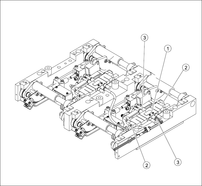
Fig. 6.11.11 Replacing the 5/3 solenoid valve
Key
Æ Move the PCB conveyor to the position which gives you the best access to the lifting table unit.
Æ Move the Y-gantries into the area outside the PCB conveyor.
Æ Turn the machine off at the main switch and disconnect the machine from the mains voltage.
Æ Make sure the machine has been properly secured to prevent it being switched on again during
servicing.
(1) Solenoid valve with 2 fastening screws (3) Pneumatic connections
(2) Connection plug