Service Manual HS60.pdf - 第189页
Se rv ice M a nu al HS-6 0 6 Mo du la r P CB con ve y or s yst em 03/ 200 3 U S Iss ue 6.11 Li ftin g table 187 6.1 1 .5.1 Par ts – 00363079 -01 light barrier f or track A - du al c o nveyor – 00363080 -01 light barrier …
6 Modular PCB conveyor system Service Manual HS-60
6.11 Lifting table 03/2003 US Issue
186
6.11.5 Replacing the fork light barrier (00363079-01)
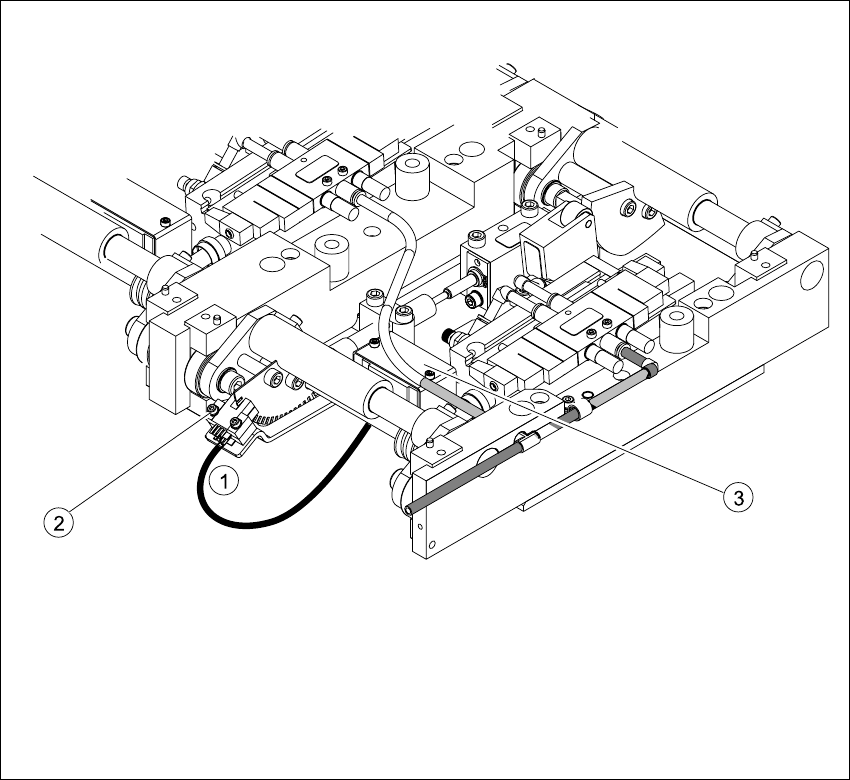
Fig. 6.11.12 Replacing the fork light barrier
Key
(1) Connection cable for the conversion board
of the lifting table
(3) Conversion board of the lifting table (under
the
cover)
(2) 2 x fork light barrier (position measuring
system tracks A + B)

Service Manual HS-60 6 Modular PCB conveyor system
03/2003 US Issue 6.11 Lifting table
187
6.11.5.1 Parts
– 00363079-01 light barrier for track A - dual conveyor
– 00363080-01 light barrier for track B - dual conveyor
– 00363111-01 light barrier for track A - single conveyor
– 00363113-01 light barrier for track B - single conveyor
6.11.5.2 Removal
Æ Move the PCB conveyor to the position which gives you the best access to the lifting table unit.
Æ Move the Y-gantries into the area outside the PCB conveyor.
Æ Turn the machine off at the main switch and disconnect the machine from the mains voltage.
Æ Make sure the machine has been properly secured to prevent it being switched on again during
servicing.
Æ Undo the screws fastening the lifting table plate and remove the lifting table plate from the lift-
ing table unit.See also Fig. 6.11.9
Æ Undo the two screws fastening the fork light barrier.
Æ Remove the cover from the conversion board of the lifting table.
Æ Unplug the conversion board of the lifting table.
Æ Install the new fork light barrier and reconnect the system to the electrical supply.
6 Modular PCB conveyor system Service Manual HS-60
6.11 Lifting table 03/2003 US Issue
188
6.11.6 Replacing the PCB clamping device sensor BB1/BB2 (00368272-01)
6.11.6.1 Function
The sensor indicates that the lifting table has activated the PCB clamping device.
The PCB is raised for placement and pressed against the PCB hold-down device (guide rail at the
side). As the lifting table moves upwards, the supporting plates on the sides raise the PCB with
the complete conveyor drive and clamp it in place. This enables the placement level to remain
constant, irrespective of the PCB thickness i.e. the placement height of the PCB remains un-
changed.
PCBs up to a length of 460 mm are clamped down in the relevant processing areas. No clamping
takes place in the input and output conveyors. PCBs with lengths between 460 mm and 510 mm
lie on the conveyor belt and are only supported in the placement area by the lifting table.
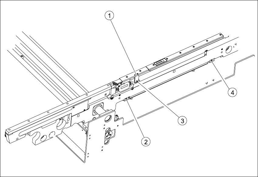
Fig. 6.11.13 Replacing the PCB clamping device sensor BB1/BB2
Key
(1) Cover with two fastening screws (behind
the sensor)
(3) Grub screw
(2) Clamping actuator 1 (4) Clamping actuator 2