Service Manual HS60.pdf - 第192页
6 Modu lar PCB conv eyor syste m Ser vic e Manu al HS- 60 6. 11 L ift ing tabl e 03/ 200 3 U S Iss ue 190 6.1 1.7 Replacin g the com plete lif ting t able cylind er (00 358703-01 ) W ARNING Before perf orming adjus tment…

Service Manual HS-60 6 Modular PCB conveyor system
03/2003 US Issue 6.11 Lifting table
189
6.11.6.2 Parts
– 00368272-01 PCB clamping device sensor BB1
– 00368273-01 PCB clamping device sensor BB2
6.11.6.3 Removal and installation
Æ Move the PCB conveyor to the position which gives you the best access to the sensor.
Æ Move the Y-gantries into the area outside the PCB conveyor.
Æ Turn the machine off at the main switch and disconnect the machine from the mains voltage.
Æ Make sure the machine has been properly secured to prevent it being switched on again during
servicing.
Æ Undo the two screws fastening the cover and remove the sensor.
Æ Weave out the connection cable and unplug it at the relevant conversion board for the con-
veyor side. (See also Fig. 6.16.33
).
Æ Place the new sensor in the area provided and replace the cover.
Æ Reconnect the electrical supply.
Æ Adjust the clamping device sensor (see also Section 6.11.6.4).
6.11.6.4 Adjusting the clamping device sensor
The clamping actuators (see Fig. 6.11.13) are arranged set so that clamping actuator 1 activates
the clamping device sensor first.
Æ To adjust the clamping device sensor, first loosen the grub screw. Then position the grub screw
so that it just touches the contact.
Æ When slight pressure is applied to the grub screw with the thumb, the input clamping sensor
should react. (SITEST -> I/O menu 3 conveyor 1 or I/O menu 4 conveyor 2, in each case on
the left under Reserve).
CAUTION
If the grub screw is over-tightened, the clamping device sensor could be destroyed.
Please check:
To rule out any unevenness on the lifting table, the clamping device sensor is checked for func-
tionality with and without the PCB and along the entire transport path. The clamping device sensor
settings are checked in continuous lifting table operation. If the clamping device sensor does not
react to the moving lifting table, an error message will be issued.
6 Modular PCB conveyor system Service Manual HS-60
6.11 Lifting table 03/2003 US Issue
190
6.11.7 Replacing the complete lifting table cylinder (00358703-01)
WARNING
Before performing adjustment work press the emergency STOP to ensure that the lifting table has
been secured against movement.
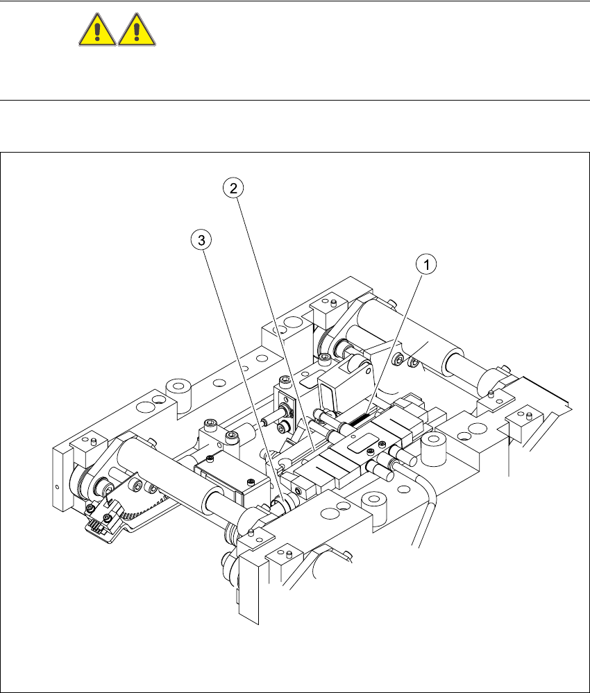
Fig. 6.11.14 Replacing the complete lifting table cylinder
Key
(1) End position proximity switch (3) Piston rod with locknut
(2) Lifting table cylinder

Service Manual HS-60 6 Modular PCB conveyor system
03/2003 US Issue 6.11 Lifting table
191
6.11.7.1 Removal/installation
Æ Move the PCB conveyor to the position which gives you the best access to the lifting table
Æ Move the Y-gantries into the area outside the PCB conveyor.
Æ Turn the machine off at the main switch and disconnect the machine from the mains voltage.
Æ Switch off the compressed air supply.
Æ Make sure the machine has been properly secured to prevent it being switched on again during
servicing.
Æ Undo the screws fastening the lifting table plate and remove the lifting table plate from the lifting
table unit.See also Fig. 6.11.9
Æ Undo the fastening screws for the solenoid valve (see also Fig. 6.11.11) and remove it from the
lifting table cylinder.
Æ Loosen the grub screw at the end position proximity switch and push the end position proximity
switch out of the lifting table cylinder guide rail.
Æ Loosen the locknut on the piston rod and twist the piston rod out until it releases itself from the
actuator.
Æ Undo and remove the two screws fastening the lifting table cylinder.
Æ Insert and fasten the new lifting table cylinder and install the piston rod.
Æ Move the lifting table by hand to its end position.
Æ Switch the machine on.
Æ Push the end position proximity switch into the guide rail until the LED lights up.
Æ Fix this position with the grub screw.
Æ Install the solenoid valve and the lifting table plate.
Æ Check the speed of the lifting table and correct where necessary (see also Section 6.11.7.2).
6.11.7.2 Adjusting the speed of the lifting table (service personnel only)
NOTE
The lifting table must be installed on the lifting table unit!
Æ Connect the service notebook to the conveyor control via the serial port.
Æ Open Start => Programs => Accessories and select the function Hyperterminal.
Æ Create a new connection.
Æ Select COM 1 => OK
Æ Select 57600 Bits/second => OK
Æ Select protocol => No => OK