Service Manual HS60.pdf - 第196页
6 Modu lar PCB conv eyor syste m Ser vic e Manu al HS- 60 6. 11 L ift ing tabl e 03/ 200 3 U S Iss ue 194 Abb . 6.1 1 - 1 7 Adju stme nt va lves o n the lif tin g tabl e cyli nder – Rotating ad justment valve t o the le …
Service Manual HS-60 6 Modular PCB conveyor system
03/2003 US Issue 6.11 Lifting table
193
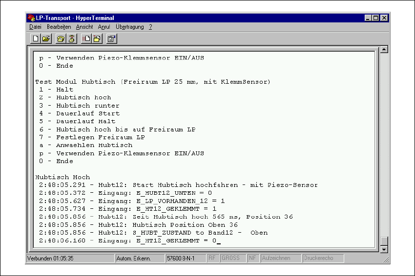
Fig. 6.11.16 Issuing times for the lifting table
Æ Adjust the valves on the lifting table cylinder to give the following values:
– Lifting table upwards: 500ms +/- 20ms
– Lifting table downwards: 480ms +/- 20ms
6 Modular PCB conveyor system Service Manual HS-60
6.11 Lifting table 03/2003 US Issue
194
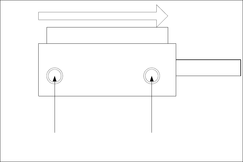
Abb. 6.11 - 17 Adjustment valves on the lifting table cylinder
– Rotating adjustment valve to the left: increases the lifting table travel time
– Rotating adjustment valve to the right: reduces the lifting table travel time
Valve setting
Time chracteristic for lifting table
below
Valve setting
Time chracteristic for lifting table
above
Transport direction
Pneumatic valve
Lifting table cylinder
Piston rod
Service Manual HS-60 6 Modular PCB conveyor system
03/2003 US Issue 6.12 Setting the fixed conveyor side (single and dual conveyor)
195
6.12 Setting the fixed conveyor side (single and dual
conveyor)
NOTE
After undoing the conveyor side fixtures you MUST check the settings for the fixed conveyor side.
If these values are not correctly set for single or dual conveyers, this could cause the placement
nest to shift out of position. This could again lead to errors in the fiducial recognition.
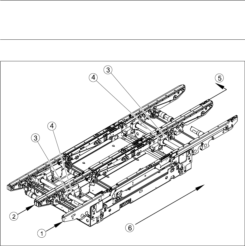
Fig. 6.12.18 Moving fixed conveyor side for conveyor track 2 (in example of S-27 HM)
Key
(1) Fixed side - conveyor track 1 (4) Fastening screw
(2) Fixed side - conveyor track 2 (5) Moving the fixed side - conveyor track 2
(3) Side flange with grub screw (6) Direction of travel