Service Manual HS60.pdf - 第201页
Se rv ic e Ma nu al HS- 6 0 6 Mo du la r P C B c onve y or s y st em 03/ 2 003 U S Iss ue 6. 13 Wi dth ad justme nt 199 F ig. 6.13 .2 1 Over v iew of widt h ad ju stm ent on th e HS- 60 Key (1) A djustm ent uni t (4) T o…

6 Modular PCB conveyor system Service Manual HS-60
6.13 Width adjustment 03/2003 US Issue
198
6.13 Width adjustment
DANGER
Please observe the safety instructions in Chapter 2.
6.13.1 Function
The width adjustment system is motor-driven with program control. For dual conveyor systems,
differing widths can be set for the two conveyor tracks. The width adjustment uses a stepping mo-
tor, meaning that the PCB width can be set independently of other machine components (e.g. the
Y-gantry). There is no end position proximity switch at the side.
The conveyor width set is fixed to a steel strip, with the help of a clamping device.
The PCB width is adjusted via two adjustment units (pneumatic cylinders), installed under the in-
put or output conveyor.
– The stepping motor moves the two adjustment units synchronously through the use of ball
screws and a toothed belt.
– To adjust the PCB width, the two adjustment units are positioned under the conveyor side con-
cerned. The exact position is determined with the help of an end position proximity switch on
the relevant adjustment unit.
– The pneumatically operated fixing pins mechanically connect the conveyor side with the ad-
justment unit. The conveyor side is unclamped (on the steel strip).
– After the new PCB width has been set, the conveyor side is reclamped and the adjustment unit
fixing pins are disconnected.
For dual conveyor systems, the widths of the transport paths are set one after the other (only one
drive unit for both conveyor tracks). Maximum and minimum PCB widths are monitored by the end
position switch. If the two conveyor sides of any one conveyor track are not parallel to one another,
this will be automatically corrected during width adjustment. The two adjustment units are then
moved under the conveyor side concerned. The adjustment unit first reaching its position under
the conveyor side fixes this. Travel continues until the second adjustment unit has also reached
its position and fixed the conveyor side.
The conveyor track has now been corrected and the two conveyor sides should be parallel. If nec-
essary, the correct PCB width can now be set.
Service Manual HS-60 6 Modular PCB conveyor system
03/2003 US Issue 6.13 Width adjustment
199
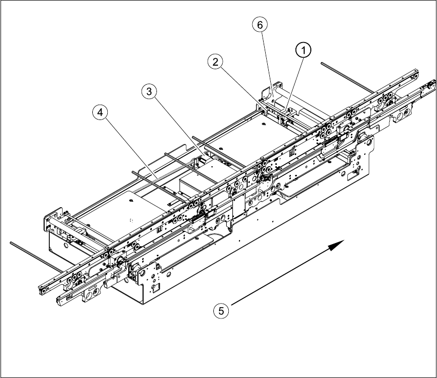
Fig. 6.13.21 Overview of width adjustment on the HS-60
Key
(1) Adjustment unit (4) Toothed belt for the width adjustment drive
(2) Synchronizing disk with spindle (5) Direction of travel
(3) Width adjustment stepping motor (6) Bearing flange
6 Modular PCB conveyor system Service Manual HS-60
6.13 Width adjustment 03/2003 US Issue
200
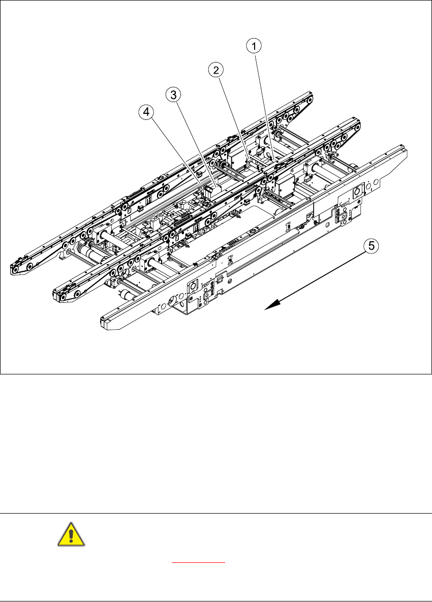
Fig. 6.13.22 Overview of width adjustment on the S-27 HM
Key
CAUTION
The bearing flange for the HS-60 (see Fig. 6.13.21
) and S-27 HM MUST NOT be loosened or ad-
justed. This would prevent the PCB conveyor from functioning and it would need to be completely
replaced.
(1) Adjustment unit (4) Toothed belt for the width adjustment drive
(2) Synchronizing disk with spindle (5) Direction of travel
(3) Width adjustment stepping motor