Service Manual HS60.pdf - 第203页
Se rv ic e Ma nu al HS- 6 0 6 Mo du la r P C B c onve y or s y st em 03/ 2 003 U S Iss ue 6. 13 Wi dth ad justme nt 201 6.13.2 Repla cing the ste pping motor of th e wid th adjustm ent sys t em (00 367174-02 ) DANGER Ple…
6 Modular PCB conveyor system Service Manual HS-60
6.13 Width adjustment 03/2003 US Issue
200
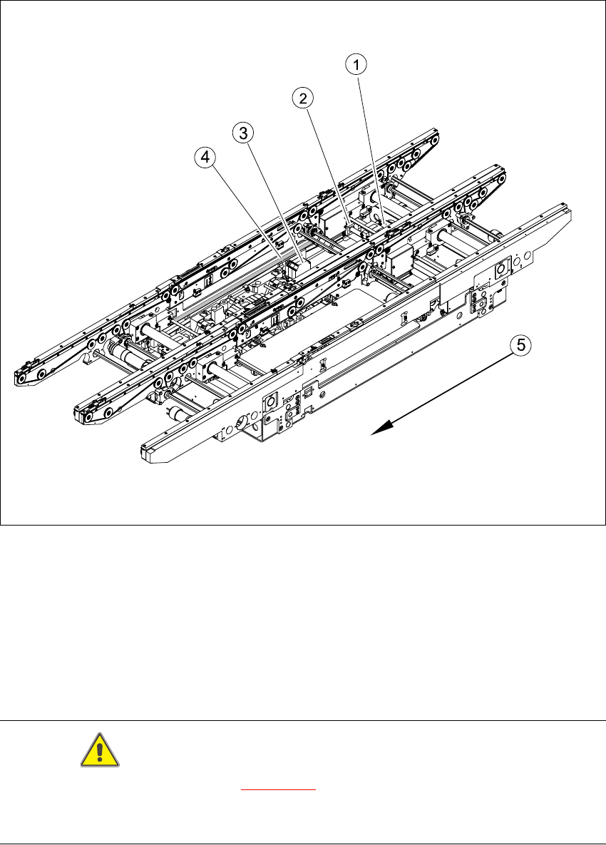
Fig. 6.13.22 Overview of width adjustment on the S-27 HM
Key
CAUTION
The bearing flange for the HS-60 (see Fig. 6.13.21
) and S-27 HM MUST NOT be loosened or ad-
justed. This would prevent the PCB conveyor from functioning and it would need to be completely
replaced.
(1) Adjustment unit (4) Toothed belt for the width adjustment drive
(2) Synchronizing disk with spindle (5) Direction of travel
(3) Width adjustment stepping motor
Service Manual HS-60 6 Modular PCB conveyor system
03/2003 US Issue 6.13 Width adjustment
201
6.13.2 Replacing the stepping motor of the width adjustment system (00367174-02)
DANGER
Please observe the safety instructions in Chapter 2.
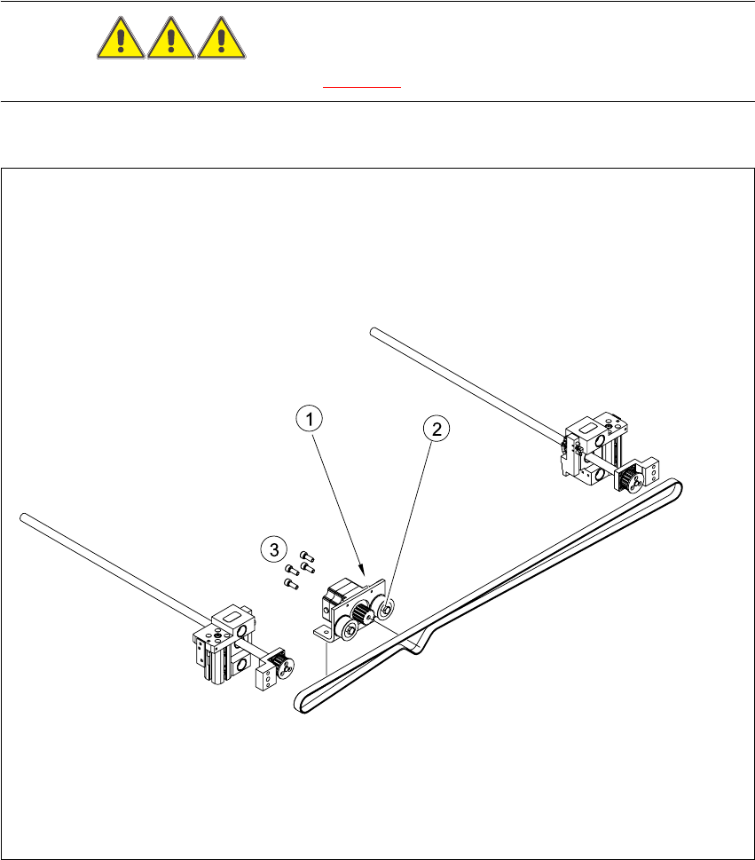
Fig. 6.13.23 Replacing the stepping motor of the width adjustment system
Key
(1) Loosening the eccentric axle on the deflec-
tion pulley
(3) Screws fastening the stepping motor
(2) Locknut on the eccentric axle

6 Modular PCB conveyor system Service Manual HS-60
6.13 Width adjustment 03/2003 US Issue
202
6.13.2.1 Removal/installation
CAUTION
During the following removal and installation of the motor, the toothed belt for the width adjustment
drive must not be stretched or kinked!
Æ Move the PCB conveyor to the position which allows you best access to the stepping motor of
the width adjustment system.
Æ Move the Y-gantries into the area outside the PCB conveyor.
Æ Turn the machine off at the main switch and disconnect the machine from the mains voltage.
Æ Make sure the machine has been properly secured to prevent it being switched on again during
servicing.
Æ Undo the screws fastening the lifting table plate and remove the lifting table plate from the lifting
table unit. See also Fig. 6.11.9
.
Æ Loosen the eccentric axle on the deflection pulley and relieve the tension on the drive belt.
Æ Remove the 4 fastening screws and then lift out the stepping motor.
Æ Unplug the connection cable in the cable duct.
Æ Install the new stepping motor and reconnect the system to the electricity supply.
Æ Tension the drive belt as described in Section 6.13.3.