Service Manual HS60.pdf - 第205页
Se rv ic e Ma nu al HS- 6 0 6 Mo du la r P C B c onve y or s y st em 03/ 2 003 U S Iss ue 6. 13 Wi dth ad justme nt 203 6.13.3 Replacing a toothe d belt f or the d rive of th e width adjust ment syste m (0035684 1-01) Fi…

6 Modular PCB conveyor system Service Manual HS-60
6.13 Width adjustment 03/2003 US Issue
202
6.13.2.1 Removal/installation
CAUTION
During the following removal and installation of the motor, the toothed belt for the width adjustment
drive must not be stretched or kinked!
Æ Move the PCB conveyor to the position which allows you best access to the stepping motor of
the width adjustment system.
Æ Move the Y-gantries into the area outside the PCB conveyor.
Æ Turn the machine off at the main switch and disconnect the machine from the mains voltage.
Æ Make sure the machine has been properly secured to prevent it being switched on again during
servicing.
Æ Undo the screws fastening the lifting table plate and remove the lifting table plate from the lifting
table unit. See also Fig. 6.11.9
.
Æ Loosen the eccentric axle on the deflection pulley and relieve the tension on the drive belt.
Æ Remove the 4 fastening screws and then lift out the stepping motor.
Æ Unplug the connection cable in the cable duct.
Æ Install the new stepping motor and reconnect the system to the electricity supply.
Æ Tension the drive belt as described in Section 6.13.3.
Service Manual HS-60 6 Modular PCB conveyor system
03/2003 US Issue 6.13 Width adjustment
203
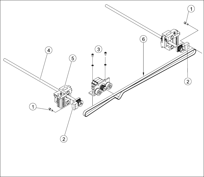
6.13.3 Replacing a toothed belt for the drive of the width adjustment system
(00356841-01)
Fig. 6.13.24 Replacing a toothed belt for the drive of the width adjustment system
Key
(1) Fastening screw on spindle block (4) Spindle
(2) Spindle block with synchronizing disk (5) Adjustment unit
(3) Stepping motor on flange (6) Measuring point of belt tension measuring
device (Strand center)
6 Modular PCB conveyor system Service Manual HS-60
6.13 Width adjustment 03/2003 US Issue
204
6.13.3.1 Removal/installation
Æ Move the PCB conveyor to the position which allows you best access to the width adjustment
system.
Æ Move the Y-gantries into the area outside the PCB conveyor.
Æ Turn the machine off at the main switch and disconnect the machine from the mains voltage.
Æ Make sure the machine has been properly secured to prevent it being switched on again during
servicing.
Æ Undo the screws fastening the lifting table plate and remove the lifting table plate from the lifting
table unit. See also Fig. 6.11.9
Æ Loosen the eccentric axle of the deflection pulley and relieve the tension on the toothed belt of
the width adjustment system drive (see also Fig. 6.13.25
).
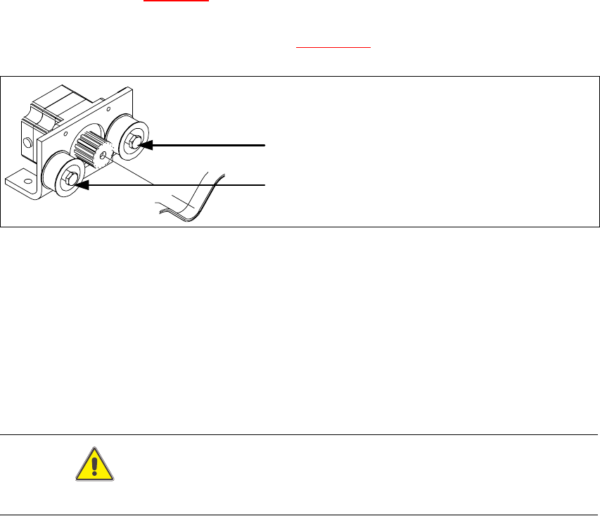
Fig. 6.13.25 Loosening the eccentric axle on the deflection pulley
Æ Undo the two fastening screws on the stepping motor flange and weave the toothed belt out of
the drive.
Æ Undo the fastening screws on the spindle block of the input or output conveyor and lift the spin-
dle block out of the locating pins. You can now remove the toothed belt from the synchronizing
disk.
Æ Undo the second spindle block and remove the toothed belt.
CAUTION
The new toothed belt must not be stretched or kinked!
Æ Place the new toothed belt on the two synchronizing disks for the spindle block and run over
the deflection pulley into the drive unit.