Service Manual HS60.pdf - 第208页
6 M odul ar PCB co nveyo r sys tem S er vice Ma nual HS-6 0 6. 13 Widt h a dj us tme nt 0 3/2 00 3 US I ss ue 206 6.13.4 Replacing the limit swit ches for the end pos ition of the wid th adjustment sys- tem (0 0365108-02…

Service Manual HS-60 6 Modular PCB conveyor system
03/2003 US Issue 6.13 Width adjustment
205
Æ Set the parallelism of the adjustment unit to the fixed side.
Æ Manually turn the spindle and place any gauge block between the adjustment unit and the
conveyor side.
Æ Turn the spindle until both adjustment units reach this limit.
Æ Check the distance on both sides with this gauge block.
Æ Tension the toothed belt (see also Fig. 6.13.24) on the eccentric axle until it engages fully with
the teeth of the synchronizing disk.
Please check: The entire width of the toothed belt must be engaged on the synchronizing disk
and must also run along the entire length of the deflection pulley.
6.13.3.2 Setting the tension of the toothed belt for the width adjustment system drive
Æ Position the measuring point of the belt tension measuring device at the strand center (i.e. the
longest distance between two synchronizing disks) of the toothed belt (see also Fig. 6.13.24
).
Æ Set the belt tension according to the following values.
– Width adjustment: 24 Hz (+/- 2 Hz)

6 Modular PCB conveyor system Service Manual HS-60
6.13 Width adjustment 03/2003 US Issue
206
6.13.4 Replacing the limit switches for the end position of the width adjustment sys-
tem (00365108-02)
DANGER
Please observe the safety instructions in Chapter 2.
Limit switch in the input conveyor:
In the vicinity of the input conveyor, there are 4 limit switches under the conveyor sides. The limit
switch is designed to prevent the conveyor sides hitting one another or the conveyor base.
Limit switch in the output conveyor:
In the vicinity of the output conveyors, there are 2 limit switches for the adjustment unit. They serve
to secure the transport area and to initialize the adjustment unit during width adjustment.
6.13.4.1 Parts
– 00365002-03 Limit switch on the mounting tray
– 00365108-02 Limit switch for width adjustment 1
– 00365109-02 Limit switch for width adjustment 2
– 00362345-01 Limit switch for width adjustment - on the conveyor side
Service Manual HS-60 6 Modular PCB conveyor system
03/2003 US Issue 6.13 Width adjustment
207
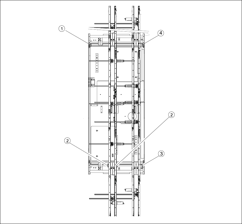
Fig. 6.13.26 Replacing the limit switch for the width adjustment system (example shows HS-60)
Key
(1) Limit switch on the mounting tray (3) Limit switch for width adjustment 1
(2) Limit switch for width adjustment 1 or 2 for
dual conveyors
(4) Limit switch for width adjustment 2