Service Manual HS60.pdf - 第210页
6 M odul ar PCB co nveyo r sys tem S er vice Ma nual HS-6 0 6. 13 Widt h a dj us tme nt 0 3/2 00 3 US I ss ue 208 6.13.4 .2 Removal/i nsta llation NOTE: The l imit swit ches are pre-assem bled and incl ude ca bles. Howev…
Service Manual HS-60 6 Modular PCB conveyor system
03/2003 US Issue 6.13 Width adjustment
207
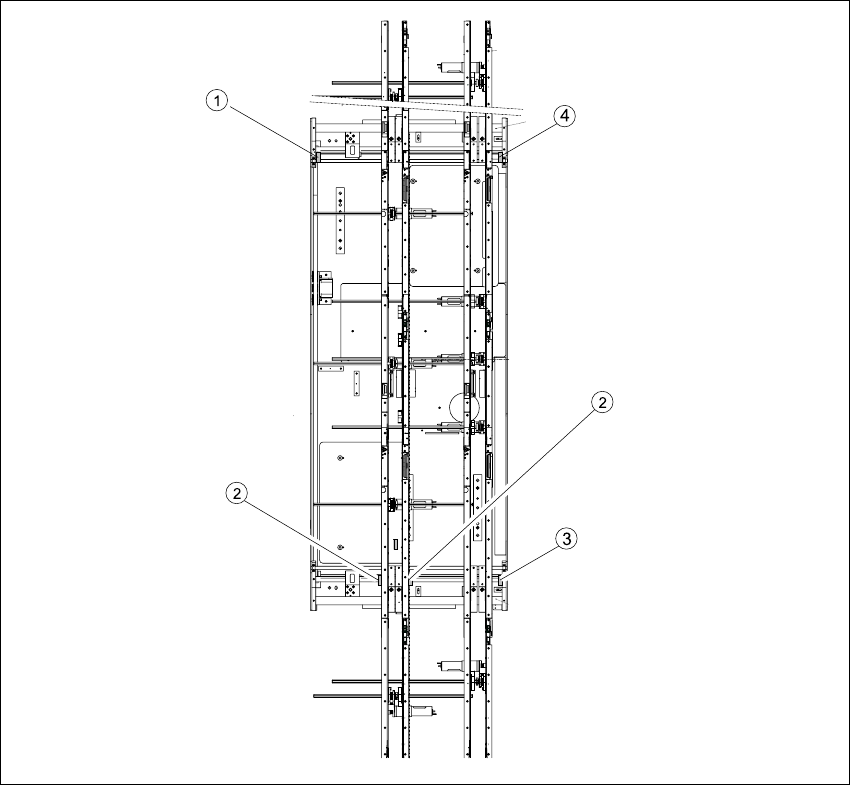
Fig. 6.13.26 Replacing the limit switch for the width adjustment system (example shows HS-60)
Key
(1) Limit switch on the mounting tray (3) Limit switch for width adjustment 1
(2) Limit switch for width adjustment 1 or 2 for
dual conveyors
(4) Limit switch for width adjustment 2

6 Modular PCB conveyor system Service Manual HS-60
6.13 Width adjustment 03/2003 US Issue
208
6.13.4.2 Removal/installation
NOTE:
The limit switches are pre-assembled and include cables.
However, if the limit switch itself is faulty, the wiring can also be unsoldered/soldered right at the
switch in question.
Æ Unsolder the connection wires on the faulty limit switch (see also Section 6.16 and Section
6.17).
Æ Undo and remove the two screws on the faulty limit switch.
NOTE:
If you have discovered a break in the limit switch cable during a continuity check, the cable must
be woven out as far as the conversion board of the mounting tray (see circuit diagrams of the
same name) and unplugged at the corresponding point. (see also Section 6.16
and Section 6.17).
This may be somewhat complicated depending on the routing of cables inside the machine base.
You may wish to contact Siemens Dematic AG SMD Service regarding this work.
Æ Install the new limit switch and re-solder the connection wires with the correct allocation.
6.13.4.3 Checking the position of the limit switch
Æ Check the minimum and maximum width for the relevant machine type and the parallelism of
the conveyor sides.
Service Manual HS-60 6 Modular PCB conveyor system
03/2003 US Issue 6.13 Width adjustment
209
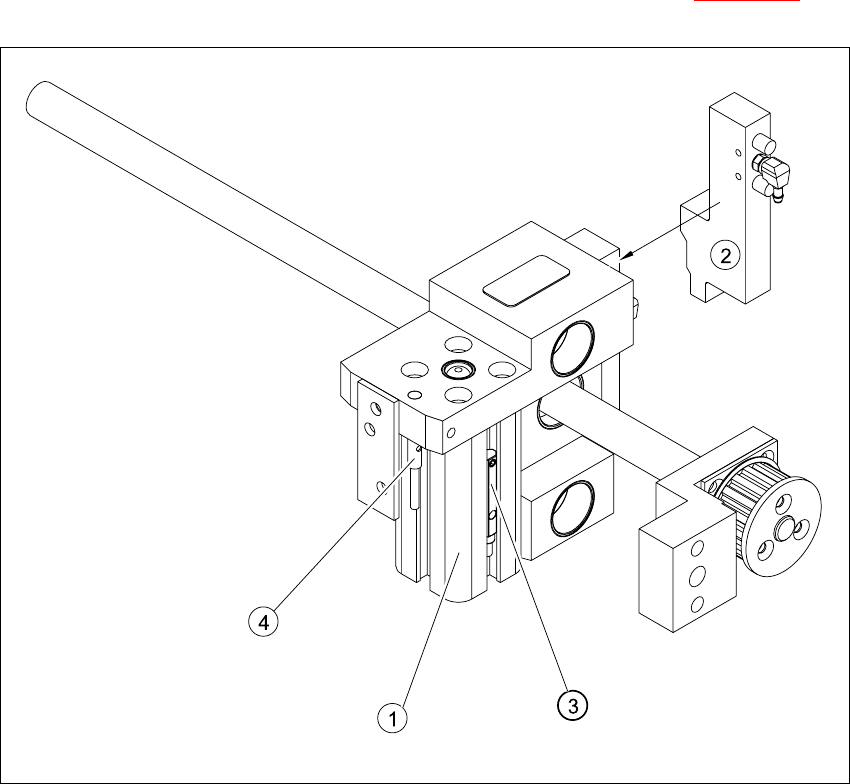
6.13.5 Adjustment unit for the width adjustment system
The position of the adjustment unit in the width adjustment system is shown in Fig. 6.13.21
Fig. 6.13.27 Overview of the adjustment unit for the width adjustment system
Key
(1) Short-stroke cylinder (3) Proximity switch
(2) Solenoid valve (4) Proximity switch for the adjustment unit