Service Manual HS60.pdf - 第215页
Se rv ic e Ma nu al HS- 6 0 6 Mo du la r P C B c onve y or s y st em 03/ 2 003 U S Iss ue 6. 13 Wi dth ad justme nt 213 6.1 3.5. 4 Rep lacin g th e actu a tor fo r the width ad justm e nt sys te m (0 03 55533 -0 2) F ig.…

6 Modular PCB conveyor system Service Manual HS-60
6.13 Width adjustment 03/2003 US Issue
212
Parts
– 00363775-01 Proximity switch adjustment unit 1
– 00363776-01 Proximity switch adjustment unit 2
Æ Move the PCB conveyor to the position which allows you best access to the adjustment unit.
Æ Move the Y-gantries into the area outside the PCB conveyor.
Æ Turn the machine off at the main switch and disconnect the machine from the mains voltage.
Æ Switch off the compressed air supply.
Æ Make sure the machine has been properly secured to prevent it being switched on again during
servicing.
Æ Loosen the grub screw on the clamping device (see also Fig. 6.13.27) and extract the connec-
tion cable as afar as the conversion board of the mounting tray.
Æ Insert the new proximity switch and reconnect to the electricity supply.
Æ Fix the proximity switch with the grub screw. The proximity switch must be level with the ad-
justment unit housing.
Æ The switching point is set at the actuator on the conveyor side.
Move the adjustment unit to under the conveyor side (see also Fig. 6.13.28
).
Æ Place a gauge block of 2/10mm on the adjustment unit, press the actuator onto the gauge
block and tighten the screw.
NOTE
This setting must be performed at all conveyor sides.
Service Manual HS-60 6 Modular PCB conveyor system
03/2003 US Issue 6.13 Width adjustment
213
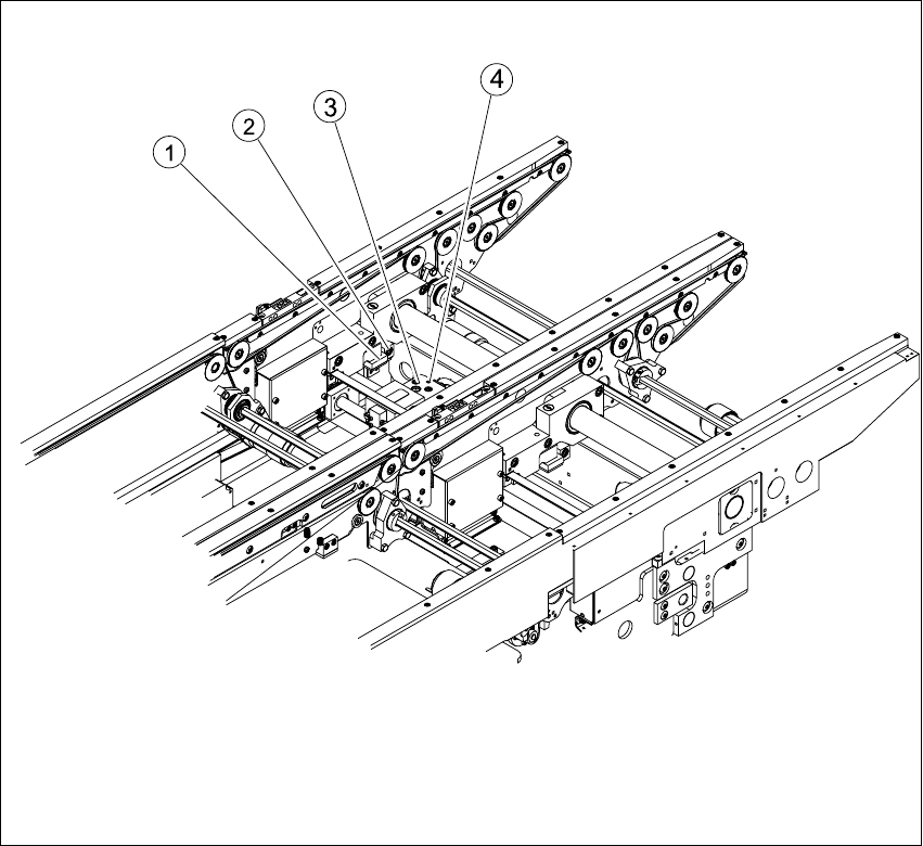
6.13.5.4 Replacing the actuator for the width adjustment system (00355533-02)
Fig. 6.13.28 Replacing the actuator for the width adjustment system
Key
Æ Move the PCB conveyor to the position which allows you best access to the adjustment unit.
Æ Move the Y-gantries into the area outside the PCB conveyor.
Æ Turn the machine off at the main switch and disconnect the machine from the mains voltage.
Æ Switch off the compressed air supply.
Æ Make sure the machine has been properly secured to prevent it being switched on again during
servicing.
(1) Actuator (3) Adjustment unit
(2) Fastening screw for actuator (4) Proximity switch for adjustment unit

6 Modular PCB conveyor system Service Manual HS-60
6.13 Width adjustment 03/2003 US Issue
214
Æ Undo and remove the screw fastening the actuator. (see also Fig. 6.13.28).
Æ Install the new actuator and screw in loosely.
Æ The switching point is set at the actuator on the conveyor side.
Move the adjustment unit to under the conveyor side.
Æ Place a gauge block of 2/10mm on the adjustment unit, press the actuator onto the gauge
block and tighten the screw.