Service Manual HS60.pdf - 第216页
6 M odul ar PCB co nveyo r sys tem S er vice Ma nual HS-6 0 6. 13 Widt h a dj us tme nt 0 3/2 00 3 US I ss ue 214 Æ Und o an d remove th e screw fastening t he actuator . (see also Fig. 6 .13 .28 ). Æ Ins tall the n ew a…
Service Manual HS-60 6 Modular PCB conveyor system
03/2003 US Issue 6.13 Width adjustment
213
6.13.5.4 Replacing the actuator for the width adjustment system (00355533-02)
Fig. 6.13.28 Replacing the actuator for the width adjustment system
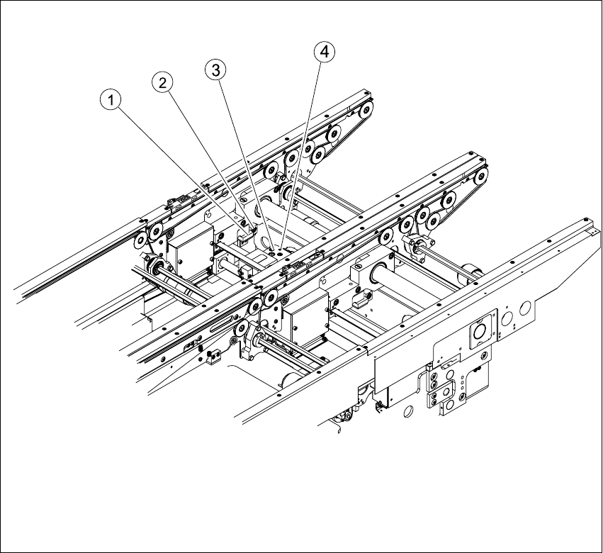
Key
Æ Move the PCB conveyor to the position which allows you best access to the adjustment unit.
Æ Move the Y-gantries into the area outside the PCB conveyor.
Æ Turn the machine off at the main switch and disconnect the machine from the mains voltage.
Æ Switch off the compressed air supply.
Æ Make sure the machine has been properly secured to prevent it being switched on again during
servicing.
(1) Actuator (3) Adjustment unit
(2) Fastening screw for actuator (4) Proximity switch for adjustment unit

6 Modular PCB conveyor system Service Manual HS-60
6.13 Width adjustment 03/2003 US Issue
214
Æ Undo and remove the screw fastening the actuator. (see also Fig. 6.13.28).
Æ Install the new actuator and screw in loosely.
Æ The switching point is set at the actuator on the conveyor side.
Move the adjustment unit to under the conveyor side.
Æ Place a gauge block of 2/10mm on the adjustment unit, press the actuator onto the gauge
block and tighten the screw.
Service Manual HS-60 6 Modular PCB conveyor system
03/2003 US Issue 6.14 Light barriers and stopper for scanning the PCB positions along the transport routes
215
6.14 Light barriers and stopper for scanning the PCB
positions along the transport routes
6.14.1 Function
The positions of the PCBs are scanned with the help of light barriers (transmitter and receiver
modules). The light barriers are installed above the conveyor belt and feel along the length of the
conveyor belt.
The light barrier signal stops the PCBs on the input conveyor, intermediate conveyor (HS-60 only)
and output conveyors. The light barrier in the placement area can be moved 50 mm against the
direction of transport to guarantee secure positioning of the PCB.
In the placement area the light barrier triggers the braking procedure via a DC motor. The soft-
ware regulates a constant time interval for the slow travel towards the laser light barrier.