Service Manual HS60.pdf - 第218页
6 M odul ar PCB co nveyo r sys tem S er vice Ma nual HS-6 0 6. 14 Li ght bar rie r s and st o ppe r fo r s ca nnin g t he PCB pos iti on s al on g the tra ns por t rou t es 03/2 00 3 US Iss ue 216 6.14.2 Rep lacin g the …
Service Manual HS-60 6 Modular PCB conveyor system
03/2003 US Issue 6.14 Light barriers and stopper for scanning the PCB positions along the transport routes
215
6.14 Light barriers and stopper for scanning the PCB
positions along the transport routes
6.14.1 Function
The positions of the PCBs are scanned with the help of light barriers (transmitter and receiver
modules). The light barriers are installed above the conveyor belt and feel along the length of the
conveyor belt.
The light barrier signal stops the PCBs on the input conveyor, intermediate conveyor (HS-60 only)
and output conveyors. The light barrier in the placement area can be moved 50 mm against the
direction of transport to guarantee secure positioning of the PCB.
In the placement area the light barrier triggers the braking procedure via a DC motor. The soft-
ware regulates a constant time interval for the slow travel towards the laser light barrier.
6 Modular PCB conveyor system Service Manual HS-60
6.14 Light barriers and stopper for scanning the PCB positions along the transport routes 03/2003 US Issue
216
6.14.2 Replacing the light barriers for transmitter and receiver modules
(ab 00370063-01)
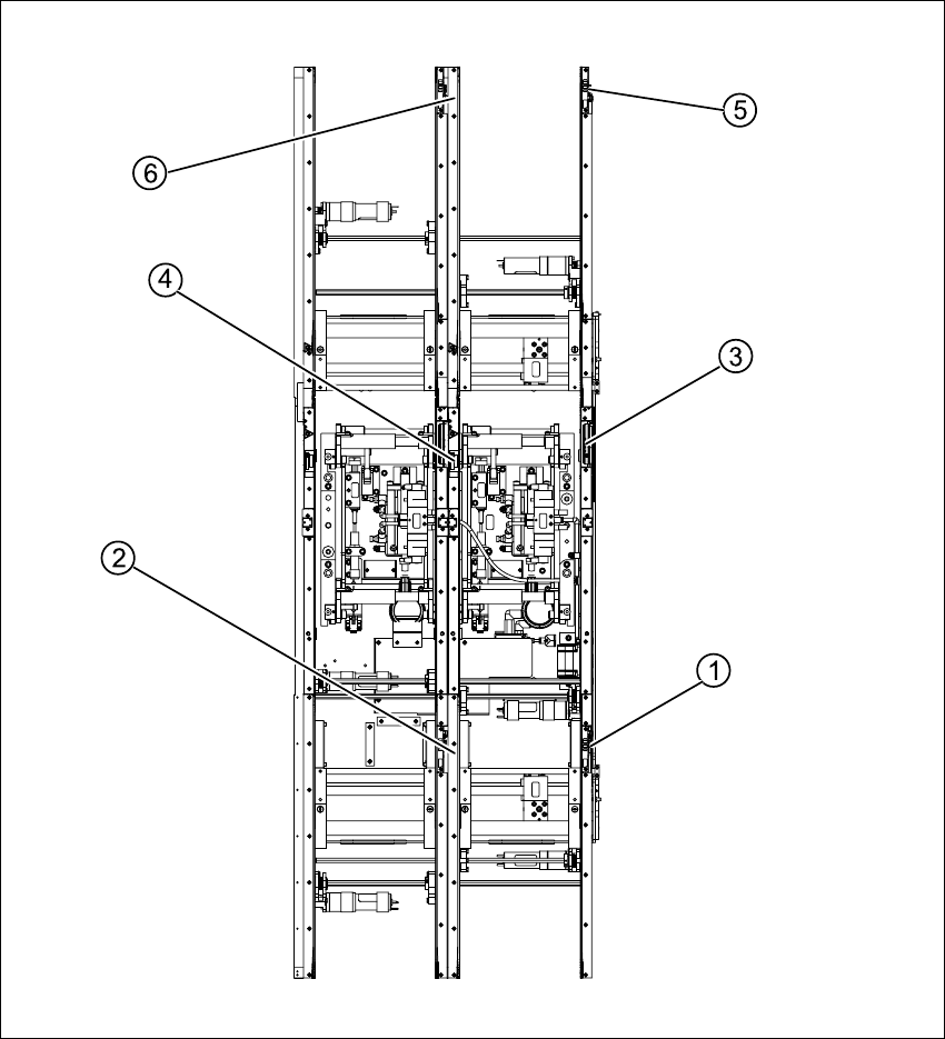
Fig. 6.14.29 Light barriers for transmitter and receiver modules (example shows S-27 HM)
Key
(1) Transmitter on input conveyor (4) Receiver on placement area
(2) Receiver on input conveyor (5) Transmitter on output conveyor
(3) Transmitter on placement area (6) Receiver on output conveyor

Service Manual HS-60 6 Modular PCB conveyor system
03/2003 US Issue 6.14 Light barriers and stopper for scanning the PCB positions along the transport routes
217
6.14.2.1 Parts
NOTE
Please note the different item numbers for the individual light barriers. These are for the different
lengths of the connection cable.
Please refer to the relevant spare parts catalogue for the different S-27 HM item numbers.
– 00370063-01 Light barrier transmitter input conveyor
– 00370064-01 Light barrier transmitter placement area1
– 00370065-01 Light barrier transmitter intermediate conveyor (HS-60 only)
– 00370066-01 Light barrier transmitter placement area 2 (HS-60 only)
– 00370067-01 Light barrier transmitter output conveyor
– 00370068-01 Light barrier receiver input conveyor
– 00370069-01 Light barrier receiver placement area1
– 00370070-01 Light barrier receiver intermediate conveyor (HS-60 only)
– 00370071-01 Light barrier receiver placement area 2 (HS-60 only)
– 00370072-01 Light barrier receiver output conveyor
6.14.2.2 Important instructions for replacing the light barrier
– The transmitter is installed on the fixed side of standard conveyor models, while the receiver
is on the moveable side.
– Check whether it would be helpful to feed in the new cable with the aid of the old one, as least
in some areas.
– The connection plug is equipped with contacts, which are pressed onto the wires. You may find
it helpful to remove the contacts from the connection plug, in order to run the cable better
through openings.
– For replacement purposes, the connection cable must be woven out as far as the relevant con-
version board of the conveyor side. This may be somewhat complicated depending on the rout-
ing of cables inside the machine base.
Either contact Siemens Dematic AG SMD Service regarding this work or proceed as follows: