Service Manual HS60.pdf - 第224页
6 M odul ar PCB co nveyo r sys tem S er vice Ma nual HS-6 0 6. 14 Li ght bar rie r s and st o ppe r fo r s ca nnin g t he PCB pos iti on s al on g the tra ns por t rou t es 03/2 00 3 US Iss ue 222 F ig. 6. 14.3 0 La se r…

Service Manual HS-60 6 Modular PCB conveyor system
03/2003 US Issue 6.14 Light barriers and stopper for scanning the PCB positions along the transport routes
221
6.14.3 Replacing the laser light barriers for stopper positions (00364782-01)
6.14.3.1 Functions
The PCB is stopped in the placement area with the aid of a laser light barrier. As soon as the light
barrier detects the front edge of an approaching PCB, the PCB is stopped. This method avoids
the impact previously caused when the PCB reached the stopper.
The position accuracy of the stopped PCB is +/-0,5 mm.
The S-27 HM is designed for the placement of longer PCBs but it does not have 2 stopping posi-
tions as in the case of HS-60. The situation is therefore different in the S-27 HM, as the machine
gantry has a larger travel range and can reach any position on the PCB. The PCB does not need
to be moved to the second stopping position in order to perform placement work on the rear area
of the PCB.
DANGER
The laser light barrier emits class 2 laser beams. These do not require any additional safety mea-
sures!
However, DO NOT expose your eyes to the laser beam!
Since laser beam deviation is at its greatest during maximum conveyor width, we recommend a
comparison at maximum conveyor width.
NOTE
After setting the laser light barrier you must check or re-teach the laser light barrier!
6 Modular PCB conveyor system Service Manual HS-60
6.14 Light barriers and stopper for scanning the PCB positions along the transport routes 03/2003 US Issue
222
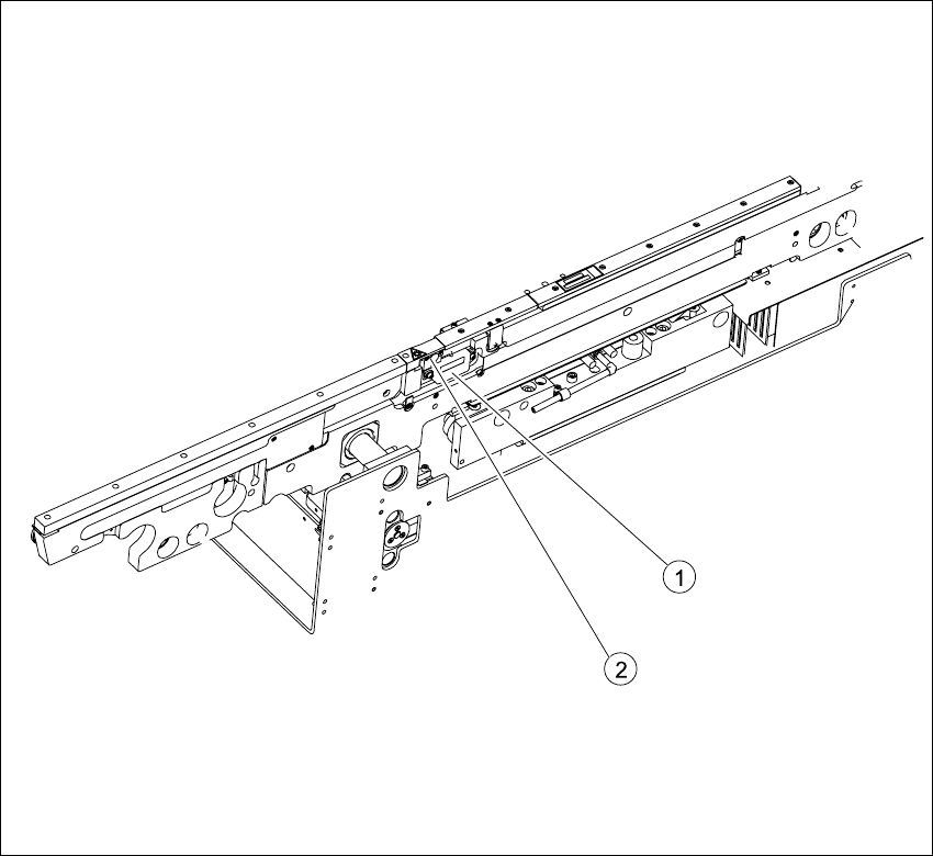
Fig. 6.14.30 Laser light barrier for stopper positions
Key
6.14.3.2 Parts
– 00364782-01 Laser light barrier for transmitter module BB1
– 00364782-01 Laser light barrier for transmitter module BB2
(1) Transmitter module (amplifier) with 2
screws
(2) Transmitter module (round laser diode)
with 3 screws

Service Manual HS-60 6 Modular PCB conveyor system
03/2003 US Issue 6.14 Light barriers and stopper for scanning the PCB positions along the transport routes
223
6.14.3.3 Removal/installation
NOTE
Since laser beam deviation is at its greatest during maximum conveyor width, we recommend a
comparison at maximum conveyor width.For laser diode settings, use the input/output function of
the SITEST program to activate the laser diode.
Æ Move the PCB conveyor to the position which allows you best access to the laser light barrier.
Æ Move the Y-gantries into the area outside the PCB conveyor.
Æ Turn the machine off at the main switch and disconnect the machine from the mains voltage.
Æ Make sure the machine has been properly secured to prevent it being switched on again during
servicing.
Æ Undo the 2 fastening screws on the large transmitter module and the 3 fastening screws on
the small transmitter module.
Æ Weave out the connection cable as far as the relevant conversion board of the conveyor side.
Æ Unplug the conversion board of the conveyor side.
Æ Rerun the connection cable accordingly and reconnect the conversion board of the conveyor
side to the electricity supply.
Æ Fix the new light barrier in the original position.
Æ Switch the machine on.
6.14.3.4 Setting and checking the laser light barrier for the stopper positions
Æ Set the maximum conveyor width.
Æ Activate the relevant laser diode via the SITEST input/output function.
Æ Check the path of the laser beam. To do this, you might want to make the laser beam visible
with the help of a piece of white paper or a light-colored PCB (see Fig. 6.14.31
).
Æ Use the three adjustment screws to set the laser beam to the middle of the receiver.
Æ Check the placement nest and re-teach it, if necessary.
NOTE:
When you move the paper, the beam should follow the edge of the PCB as accurately as possible.
Any deviation to the left or right should be kept to a minimum.