Service Manual HS60.pdf - 第226页
6 M odul ar PCB co nveyo r sys tem S er vice Ma nual HS-6 0 6. 14 Li ght bar rie r s and st o ppe r fo r s ca nnin g t he PCB pos iti on s al on g the tra ns por t rou t es 03/2 00 3 US Iss ue 224 F ig. 6. 14.3 1 S et ti…

Service Manual HS-60 6 Modular PCB conveyor system
03/2003 US Issue 6.14 Light barriers and stopper for scanning the PCB positions along the transport routes
223
6.14.3.3 Removal/installation
NOTE
Since laser beam deviation is at its greatest during maximum conveyor width, we recommend a
comparison at maximum conveyor width.For laser diode settings, use the input/output function of
the SITEST program to activate the laser diode.
Æ Move the PCB conveyor to the position which allows you best access to the laser light barrier.
Æ Move the Y-gantries into the area outside the PCB conveyor.
Æ Turn the machine off at the main switch and disconnect the machine from the mains voltage.
Æ Make sure the machine has been properly secured to prevent it being switched on again during
servicing.
Æ Undo the 2 fastening screws on the large transmitter module and the 3 fastening screws on
the small transmitter module.
Æ Weave out the connection cable as far as the relevant conversion board of the conveyor side.
Æ Unplug the conversion board of the conveyor side.
Æ Rerun the connection cable accordingly and reconnect the conversion board of the conveyor
side to the electricity supply.
Æ Fix the new light barrier in the original position.
Æ Switch the machine on.
6.14.3.4 Setting and checking the laser light barrier for the stopper positions
Æ Set the maximum conveyor width.
Æ Activate the relevant laser diode via the SITEST input/output function.
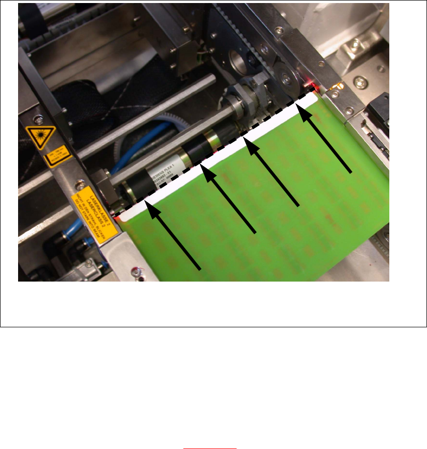
Æ Check the path of the laser beam. To do this, you might want to make the laser beam visible
with the help of a piece of white paper or a light-colored PCB (see Fig. 6.14.31
).
Æ Use the three adjustment screws to set the laser beam to the middle of the receiver.
Æ Check the placement nest and re-teach it, if necessary.
NOTE:
When you move the paper, the beam should follow the edge of the PCB as accurately as possible.
Any deviation to the left or right should be kept to a minimum.
6 Modular PCB conveyor system Service Manual HS-60
6.14 Light barriers and stopper for scanning the PCB positions along the transport routes 03/2003 US Issue
224
Fig. 6.14.31 Setting the laser beam
6.14.4 Setting the light barriers in the placement area
Function:
– Switch on the laser light barrier
– Start the PCB braking procedure, see Fig. 6.14.32
.
The light barrier in the placement area can be moved within a range of 50 mm. This function was
designed for PCBs with recesses on the side, to ensure that they are stopped by the laser light
barrier. In its standard version, the light barrier is installed in the direction of conveyor input, giving
the greatest distance between the light barrier and laser. The software automatically sets the slow
travel of the PCB so that it takes approx.
100 ms until it reaches the laser light barrier.
Service Manual HS-60 6 Modular PCB conveyor system
03/2003 US Issue 6.14 Light barriers and stopper for scanning the PCB positions along the transport routes
225
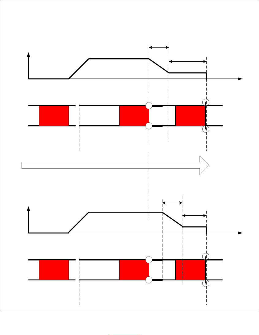
Fig. 6.14.32 Diagrams v(t), PCB braking procedure
The travel profile to brake the PCB (see Fig. 6.14.32) is initiated at the correct moment to ensure
that the PCB is stopped at the laser light barrier after a maximum of 100ms. The automatic learn-
ing process at the beginning of the travel profile ensures that the stopper position is reached in a
constant time, irrespective of the PCB weight. The transport time remains constant.
Direction of PCB transport
Time (t)
< 100 ms
Light barrier
Laser
Travel profile
braking process
Start End
Placement areaInput belt
2nd board
Time (t)
Speed (v)
150 ms
Laser
Travel profile
braking process
Start End
Input belt
1st board
Speed (v)
Placement area
Light barrier