Service Manual HS60.pdf - 第229页
Se rv ic e Ma nu al HS- 6 0 6 Mo du la r P C B c onve y or s y st em 03/ 2003 US Is sue 6. 15 C hecks t o be p erforme d afte r mech anic al wo rk on the conv eyor sys t em 227 Æ P ush one PCB manual ly through the entir…
6 Modular PCB conveyor system Service Manual HS-60
6.15 Checks to be performed after mechanical work on the conveyor system 03/2003 US Issue
226
6.15 Checks to be performed after mechanical work on
the conveyor system
DANGER
Please observe the safety instructions in Chapter 2.
Æ Check the distance between the top edge of the conveyor belt and the top of the guide rail.
This measurement should be 6 mm.
Æ Check the distance between the top edge of the conveyor belt and the top of the guide rail at
the clamping sensor.
This measurement should be 5.8 mm.
Æ Check the distance between the actuator clamping device (lifting table) and the top edge of the
belt.
This measurement should be 94.2 mm for the HS-60.
This measurement should be 74.2 mm for the S-27 HM.
Æ Check the distance between the actuator clamping device (lifting table) and the top edge of the
belt at the clamping sensor.
This measurement should be 94.4 mm for the HS-60.
This measurement should be 74.2 mm for the S-27 HM
TIP
Move one PCB into the placement area and clamp the PCB in place. Now measure the distance
between the top edge of the lifting table (rubber stop) and the bottom edge of the PCB. This height
should be exactly 94 mm for the HS-60 and 74 mm for the S-27 HM.
NOTE
The actuator under the clamping sensor must be mounted 0.2 - 0.3 mm lower to guarantee reliable
actuation of the clamping sensor.
Service Manual HS-60 6 Modular PCB conveyor system
03/2003 US Issue 6.15 Checks to be performed after mechanical work on the conveyor system
227
Æ Push one PCB manually through the entire PCB conveyor system and make sure that it
moves easily through the entire system.
Place a PCB in the previous station at the input point and transport it with the relevant functions
through all 5 transport areas - all the way to the next PCB or to the output point.
6 Modular PCB conveyor system Service Manual HS-60
6.16 Overview of the electrical components 03/2003 US Issue
228
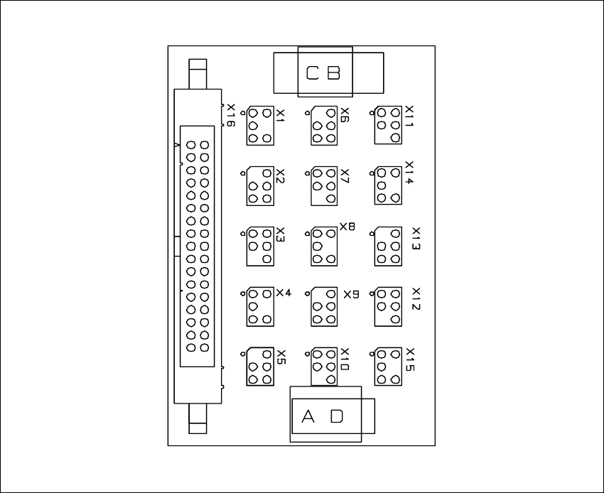
6.16 Overview of the electrical components
6.16.1 Conversion board of the conveyor side (00359424-01)
Fig. 6.16.33 Conversion board of the conveyor side (00359424-01)