Service Manual HS60.pdf - 第255页
HS -60 Se rvic e Ma nual 7 DLM2 Co l lect&Plac e Head 03/ 2 003 U S Iss ue 7. 2 S truc tu re of th e c o lle c t&p lac e head 253 7.2. 4 SP_12 D igit al int ermediate d istrib ution bo ard (0 0330648- 05) 7 F ig.…
7 DLM2 Collect&Place Head HS-60 Service Manual
7.2 Structure of the collect&place head 03/2003 US Issue
252
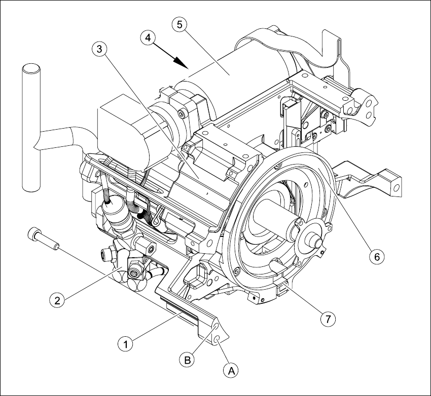
7.2.3 Front part, complete / DLM2
The front part is centered by two holes (item B) into which the parallel pins of the back part engage.
The front is fixed to the back part with four M4x16 hexagon-socket head screws (item A). 7
7
Fig. 7.2 - 3 Structure of the front part / DLM2
(1) Casing / DLM2
(2) Forced air unit / DLM2
(3) RSF digital rotary encoder / DLM2 (beneath the board with the protective cover)
(4) Star drive, digital / DLM2
(5) Z-axis drive
(6) Raceway for the 12 ball bearings on the segments
(7) Snap jaws raising or lowering the sleeve
HS-60 Service Manual 7 DLM2 Collect&Place Head
03/2003 US Issue 7.2 Structure of the collect&place head
253
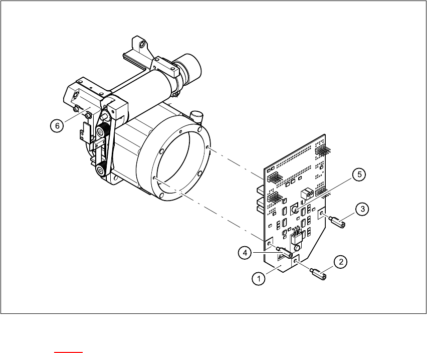
7.2.4 SP_12 Digital intermediate distribution board (00330648-05)
7
Fig. 7.2 - 4 SP6_12 intermediate distribution board, digital
Key to Fig. 7.2 - 4
(1) Intermediate distribution board
(2) M3x10 spacer bolt
(3) M3x7 spacer bolt
(4) M3x9 spacer bolt
(5) M3x5 hexagon-socket head screw
(6) Front part of the collect&place head
7
The intermediate distribution board (1) is fixed to the front part (4) with three spacer bolts (items
2, 3 and 4) and one M3x5 hexagon-socket head screw (item 5). 7
Two 40-pin ribbon cables run from plug X1 and X2 on the intermediate distribution board to socket
X14 / X13 on the head board. 7
