Service Manual HS60.pdf - 第256页
7 DL M2 Co llec t &P lace Head H S-6 0 S erv ic e Manu al 7. 2 S tru ct ur e of th e col lec t& p la ce h ea d 03/ 2 003 U S I ssue 254 7 F ig. 7. 2 - 5 I nte rm ed ia te di str ib uto r - po si tio n of th e s o…
HS-60 Service Manual 7 DLM2 Collect&Place Head
03/2003 US Issue 7.2 Structure of the collect&place head
253
7.2.4 SP_12 Digital intermediate distribution board (00330648-05)
7
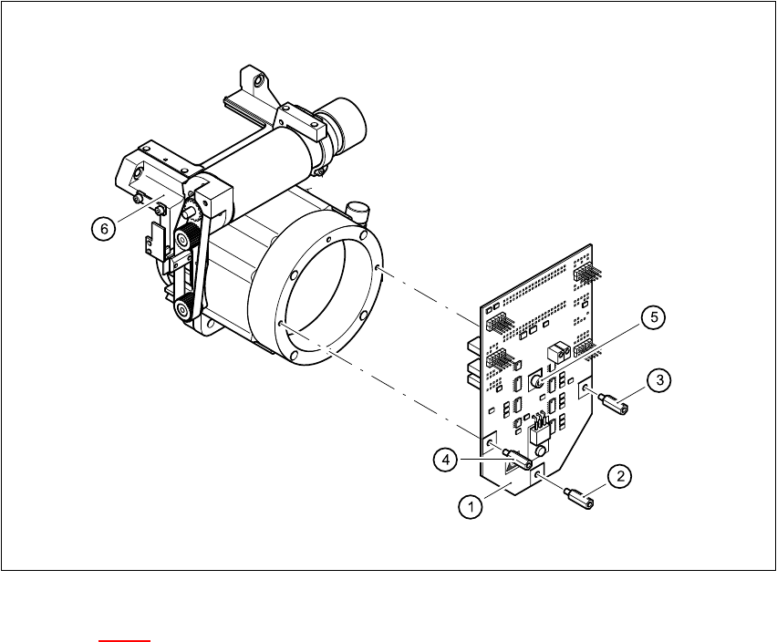
Fig. 7.2 - 4 SP6_12 intermediate distribution board, digital
Key to Fig. 7.2 - 4
(1) Intermediate distribution board
(2) M3x10 spacer bolt
(3) M3x7 spacer bolt
(4) M3x9 spacer bolt
(5) M3x5 hexagon-socket head screw
(6) Front part of the collect&place head
7
The intermediate distribution board (1) is fixed to the front part (4) with three spacer bolts (items
2, 3 and 4) and one M3x5 hexagon-socket head screw (item 5). 7
Two 40-pin ribbon cables run from plug X1 and X2 on the intermediate distribution board to socket
X14 / X13 on the head board. 7


HS-60 Service Manual 7 DLM2 Collect&Place Head
03/2003 US Issue 7.2 Structure of the collect&place head
255
The following supply voltages and signals are routed by the intermediate distribution board to the
individual placement head modules or to the head board: 7
Plug X1, 40-pin (see Fig. 7.2 - 5) 7
Connected to plug X14 on the head board 7
– Voltage supply, tacho and track signals for the Z-axis drive
– Signal from light barrier "Z-axis in top position"
– Signal from light barrier "Z-axis in bottom position" (sensor stop signal)
– Control signal for the forced air valve
– Supply voltage + 5VDC, ± 15VDC
– Reference point signal for the DP-axis
– Track signals for the DP-axis
Plug X2, 40-pin (see Fig. 7.2 - 5) 7
Connected to plug X13 on the head board 7
– Voltage supply and track signals for the star-axis drive
– Reference point for the star-axis
– Analog forced air pressure value
– Supply voltages + 5 VDC, ± 15VDC, + 24VDC
Plug X3, 10-pin (see Fig. 7.2 - 5) 7
Connection for the Z-motor and Z-tacho signal 7
Plug X4, 10-pin (see Fig. 7.2 - 5) 7
Connection for the Z-axis track signals 7
Plug X5, 10-pin (see Fig. 7.2 - 5) 7
Connection for the star motor 7
Plug X6, 6-pin (see Fig. 7.2 - 5) 7
Connection for the forced air valve 7
Plug X7, 10-pin (see Fig. 7.2 - 5) 7
Connection for the DP-axis track signals 7