Service Manual HS60.pdf - 第258页
7 DL M2 Co llec t &P lace Head H S-6 0 S erv ic e Manu al 7. 2 S tru ct ur e of th e col lec t& p la ce h ea d 03/ 2 003 U S I ssue 256 Plu g X1 0, 10 -pi n (see Fig . 7.2 - 5 ) 7 Connec tion for the "Z-axis…

HS-60 Service Manual 7 DLM2 Collect&Place Head
03/2003 US Issue 7.2 Structure of the collect&place head
255
The following supply voltages and signals are routed by the intermediate distribution board to the
individual placement head modules or to the head board: 7
Plug X1, 40-pin (see Fig. 7.2 - 5) 7
Connected to plug X14 on the head board 7
– Voltage supply, tacho and track signals for the Z-axis drive
– Signal from light barrier "Z-axis in top position"
– Signal from light barrier "Z-axis in bottom position" (sensor stop signal)
– Control signal for the forced air valve
– Supply voltage + 5VDC, ± 15VDC
– Reference point signal for the DP-axis
– Track signals for the DP-axis
Plug X2, 40-pin (see Fig. 7.2 - 5) 7
Connected to plug X13 on the head board 7
– Voltage supply and track signals for the star-axis drive
– Reference point for the star-axis
– Analog forced air pressure value
– Supply voltages + 5 VDC, ± 15VDC, + 24VDC
Plug X3, 10-pin (see Fig. 7.2 - 5) 7
Connection for the Z-motor and Z-tacho signal 7
Plug X4, 10-pin (see Fig. 7.2 - 5) 7
Connection for the Z-axis track signals 7
Plug X5, 10-pin (see Fig. 7.2 - 5) 7
Connection for the star motor 7
Plug X6, 6-pin (see Fig. 7.2 - 5) 7
Connection for the forced air valve 7
Plug X7, 10-pin (see Fig. 7.2 - 5) 7
Connection for the DP-axis track signals 7
7 DLM2 Collect&Place Head HS-60 Service Manual
7.2 Structure of the collect&place head 03/2003 US Issue
256
Plug X10, 10-pin (see Fig. 7.2 - 5) 7
Connection for the "Z-axis up" signal 7
Plug X11, 8-pin (see Fig. 7.2 - 5) 7
Connection for the light barrier "Z-axis down" signal (sensor stop signal) 7
Plug X12, 10-pin (see Fig. 7.2 - 5) 7
Connection for the star-axis track signals 7
7.2.5 24x24 component camera
7
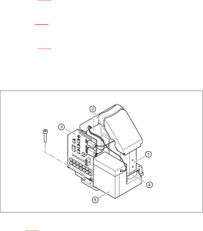
Fig. 7.2 - 6 24x24 component camera
Key to Fig. 7.2 - 6
(1) 24x24 component camera
(2) Deflecting mirror (under the protective cover)
(3) Illumination control board for the three LED planes:
flat, medium and steep 7
(4) Lens module and XC75 180 camera
(5) Camera amplifier
HS-60 Service Manual 7 DLM2 Collect&Place Head
03/2003 US Issue 7.2 Structure of the collect&place head
257
7
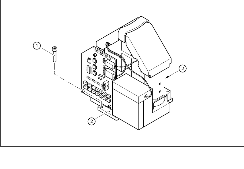
Fig. 7.2 - 7 Fixing the component camera
Key to Fig. 7.2 - 7
(1) 4 x M4x10 hexagon-socket head screws
(2) 2 x M5x6 parallel pins
7
The component camera is fixed to the front part of the collect&place head with four M4x10 hexa-
gon-socket head screws (item 1). It is also centered on the casing with two M5x6 parallel pins
(item 2). 7