Service Manual HS60.pdf - 第260页
7 DL M2 Co llec t &P lace Head H S-6 0 S erv ic e Manu al 7. 3 P art s ov erv ie w 0 3/2 003 U S I ssue 258 7. 3 Part s overview 7 Fig . 7.3 - 1 DLM2 col lect &pl ace he ad - pa rt s over view 1 It em i n Fig . 7…
HS-60 Service Manual 7 DLM2 Collect&Place Head
03/2003 US Issue 7.2 Structure of the collect&place head
257
7
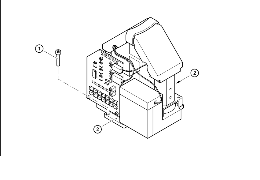
Fig. 7.2 - 7 Fixing the component camera
Key to Fig. 7.2 - 7
(1) 4 x M4x10 hexagon-socket head screws
(2) 2 x M5x6 parallel pins
7
The component camera is fixed to the front part of the collect&place head with four M4x10 hexa-
gon-socket head screws (item 1). It is also centered on the casing with two M5x6 parallel pins
(item 2). 7
7 DLM2 Collect&Place Head HS-60 Service Manual
7.3 Parts overview 03/2003 US Issue
258
7.3 Parts overview
7
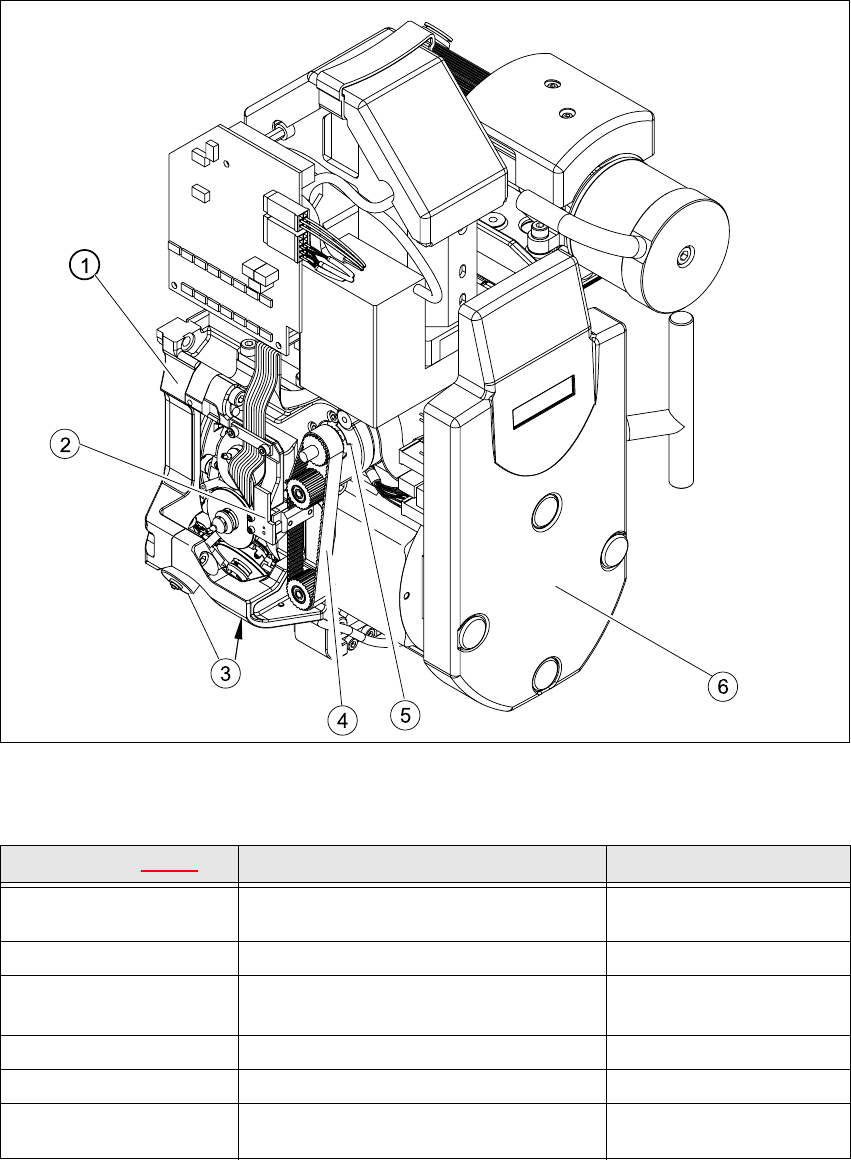
Fig. 7.3 - 1 DLM2 collect&place head - parts overview 1
Item in Fig. 7.3 - 1 Designation Item no.
1
Collect&place head SP12 complete / DLM2
Collect&place head SP6 complete / DLM2
00367281-02
00367020-01
2 Light barrier for "Z-axis up" 00347297-01
3
Valve positioning drive, placement circuit
Valve positioning drive, reject circuit
00368075-01
00367768-01
4 Toothed belt T2 / DLM2 00334936-01
5 Z-axis drive / DLM2 00341011-01
6
SP6_12 intermediate distribution board, digi-
tal 00330648-05
HS-60 Service Manual 7 DLM2 Collect&Place Head
03/2003 US Issue 7.3 Parts overview
259
7
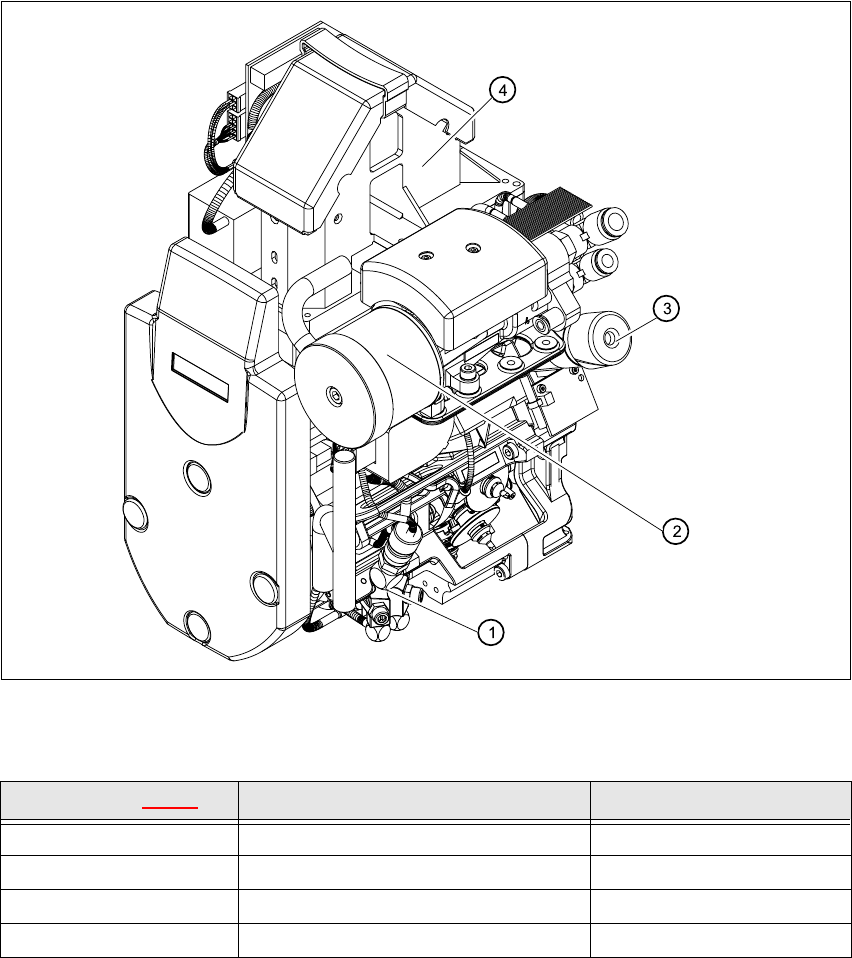
Fig. 7.3 - 2 DLM2 collect&place head - parts overview 2
Item in Fig. 7.3 - 2 Designation Item no.
1 Forced air unit / DLM2 00367793-01
2 Silencer 03003134-01
3 Turning station / DLM2 00341780-03
424x24 component camera KST 00336791-03