Service Manual HS60.pdf - 第264页
7 DL M2 Co llec t &P lace Head H S-6 0 S erv ic e Manu al 7.4 P oin ts to no te bef ore st art ing s ervici ng work ... 03/ 2003 US Is sue 262 – The T a g Out alternative: If a m achine can be locked o ut, it must be…
HS-60 Service Manual 7 DLM2 Collect&Place Head
03/2003 US Issue 7.4 Points to note before starting servicing work ...
261
7.4 Points to note before starting servicing work ...
Æ End all placement operations on the placement system.
Æ Switch the placement system off at the main switch.
Æ Wait, until the operating system has shut down and the UPS has switched off.
Æ Disconnect the placement system from the power supply.
Æ Disconnect the placement system from the compressed air supply.
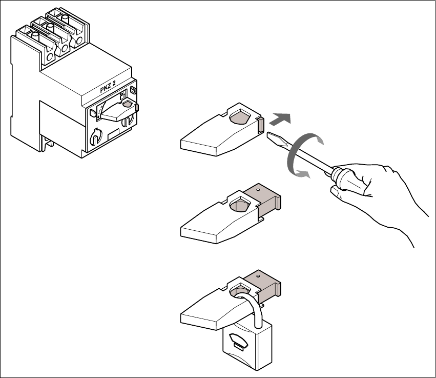
Æ Switch off the motor contactor in the power supply unit and secure the operating lever with a
padlock.
7
Fig. 7.4 - 1 Locking the motor contactor
(1) Turn the operating lever (1) counter-clockwise.
(2) Use the screwdriver to push the locking lug (2) out of the operating lever (1).
(3) Secure the operating lever with a padlock (3).

7 DLM2 Collect&Place Head HS-60 Service Manual
7.4 Points to note before starting servicing work ... 03/2003 US Issue
262
– The Tag Out alternative:
If a machine can be locked out, it must be. However, there are situations where energy isolat-
ing devices can not accommodate locks. In these cases, the energy isolating devices must be
tagged to warn employees that the machine is de-energized for servicing. The tag must be se-
curely fastened, it must be placed in a position visible to all and it may only be removed by the
person who attached it. 7
WARNING
To avoid damaging the collect&place head, ALWAYS observe the following points when
moving the gantry: 7
– NEVER move the gantry by pushing with your hands against the collect&place head.
– NEVER push the gantry while the Z-axis is lowered.
– Take hold of the cast iron part of the X-axis - ideally near the X-axis toothed belt deflection
pulley - and then move the gantry.

HS-60 Service Manual 7 DLM2 Collect&Place Head
03/2003 US Issue 7.5 Replacing the collect&place head / DLM2 (00367770-01)
263
7.5 Replacing the collect&place head / DLM2
(00367770-01)
7.5.1 Tools and equipment
– Set of DIN 911 Allen keys
– Setting instructions
– SITEST program
7.5.2 Parts
Collect&place head SP 12 complete / DLM2, item no. 00367770-01 7
7.5.3 Dismantling the collect&place head
– Switch the placement system off and secure it to prevent switching on again as described in
Section 7.4
, page 261.
– Detach the plug-in connections on the head board 00331451-xx (see Fig. 7.5 - 1
).