Service Manual HS60.pdf - 第265页
HS -60 Se rvic e Ma nual 7 DLM2 Co l lect&Plac e Head 03/ 2003 US Is sue 7. 5 Rep laci ng th e coll ect &pla ce hea d / DLM2 (003 6777 0-0 1) 263 7.5 Repla cing the c ollect& place he ad / D LM2 (003677 70-01…

7 DLM2 Collect&Place Head HS-60 Service Manual
7.4 Points to note before starting servicing work ... 03/2003 US Issue
262
– The Tag Out alternative:
If a machine can be locked out, it must be. However, there are situations where energy isolat-
ing devices can not accommodate locks. In these cases, the energy isolating devices must be
tagged to warn employees that the machine is de-energized for servicing. The tag must be se-
curely fastened, it must be placed in a position visible to all and it may only be removed by the
person who attached it. 7
WARNING
To avoid damaging the collect&place head, ALWAYS observe the following points when
moving the gantry: 7
– NEVER move the gantry by pushing with your hands against the collect&place head.
– NEVER push the gantry while the Z-axis is lowered.
– Take hold of the cast iron part of the X-axis - ideally near the X-axis toothed belt deflection
pulley - and then move the gantry.

HS-60 Service Manual 7 DLM2 Collect&Place Head
03/2003 US Issue 7.5 Replacing the collect&place head / DLM2 (00367770-01)
263
7.5 Replacing the collect&place head / DLM2
(00367770-01)
7.5.1 Tools and equipment
– Set of DIN 911 Allen keys
– Setting instructions
– SITEST program
7.5.2 Parts
Collect&place head SP 12 complete / DLM2, item no. 00367770-01 7
7.5.3 Dismantling the collect&place head
– Switch the placement system off and secure it to prevent switching on again as described in
Section 7.4
, page 261.
– Detach the plug-in connections on the head board 00331451-xx (see Fig. 7.5 - 1
).
7 DLM2 Collect&Place Head HS-60 Service Manual
7.5 Replacing the collect&place head / DLM2 (00367770-01) 03/2003 US Issue
264
7
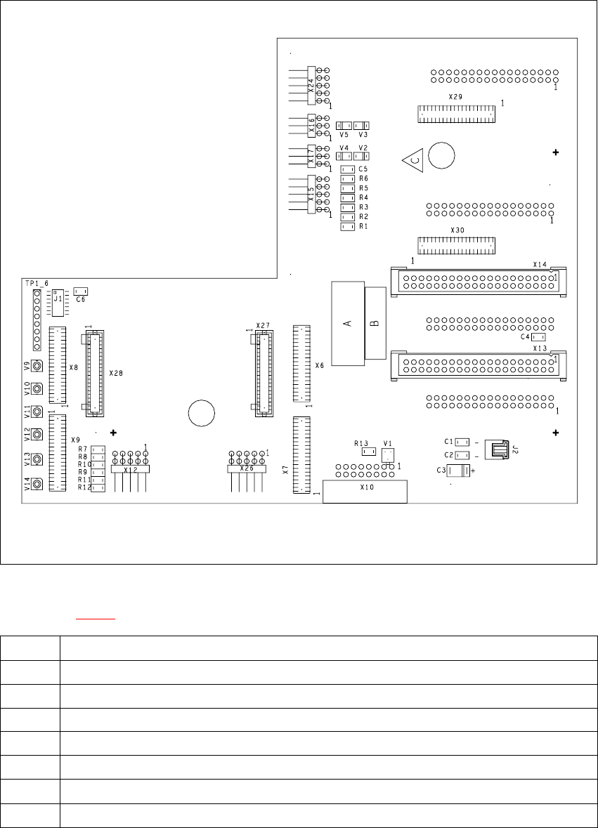
Fig. 7.5 - 1 Head board - plug-in connections
Key to Fig. 7.5 - 1
X9 For the component illumination controller and component camera
X10 For the vacuum measuring board
X12 For the DP-axis, motor and tacho
X13 For plug X2 on the intermediate distribution board
X14 For plug X1 on the intermediate distribution board
X18 For the infeed motor of the DP-axis
X19 For the "Placement circuit" valve positioning drive (star station 1)
X20 For the "Reject circuit" valve positioning drive (star station 3)
Tab. 7.5 - 1 Plug-in connections on the head board