Service Manual HS60.pdf - 第267页
HS -60 Se rvic e Ma nual 7 DLM2 Co l lect&Plac e Head 03/ 2003 US Is sue 7. 5 Rep laci ng th e coll ect &pla ce hea d / DLM2 (003 6777 0-0 1) 265 7 Fig. 7.5 - 2 Col lect &pl ace he ad - co mpre ssed a ir co n…
7 DLM2 Collect&Place Head HS-60 Service Manual
7.5 Replacing the collect&place head / DLM2 (00367770-01) 03/2003 US Issue
264
7
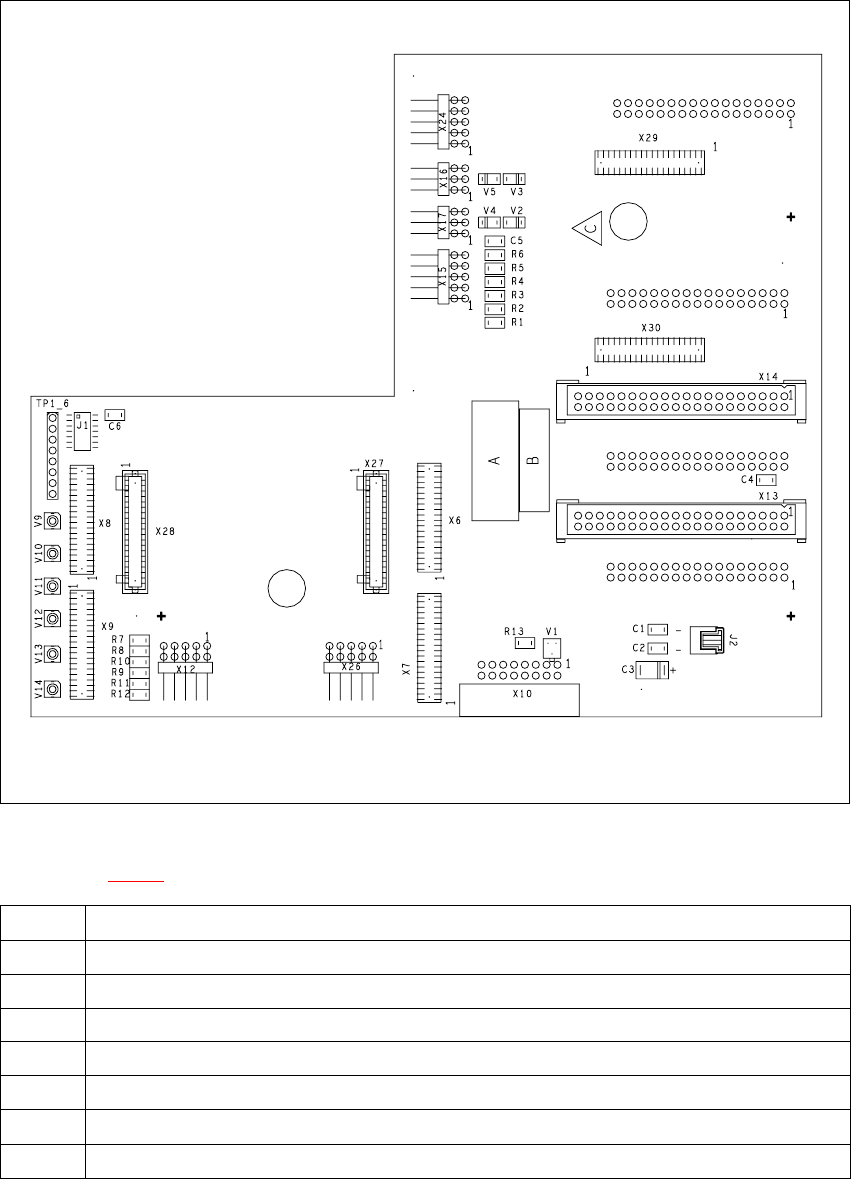
Fig. 7.5 - 1 Head board - plug-in connections
Key to Fig. 7.5 - 1
X9 For the component illumination controller and component camera
X10 For the vacuum measuring board
X12 For the DP-axis, motor and tacho
X13 For plug X2 on the intermediate distribution board
X14 For plug X1 on the intermediate distribution board
X18 For the infeed motor of the DP-axis
X19 For the "Placement circuit" valve positioning drive (star station 1)
X20 For the "Reject circuit" valve positioning drive (star station 3)
Tab. 7.5 - 1 Plug-in connections on the head board
HS-60 Service Manual 7 DLM2 Collect&Place Head
03/2003 US Issue 7.5 Replacing the collect&place head / DLM2 (00367770-01)
265
7
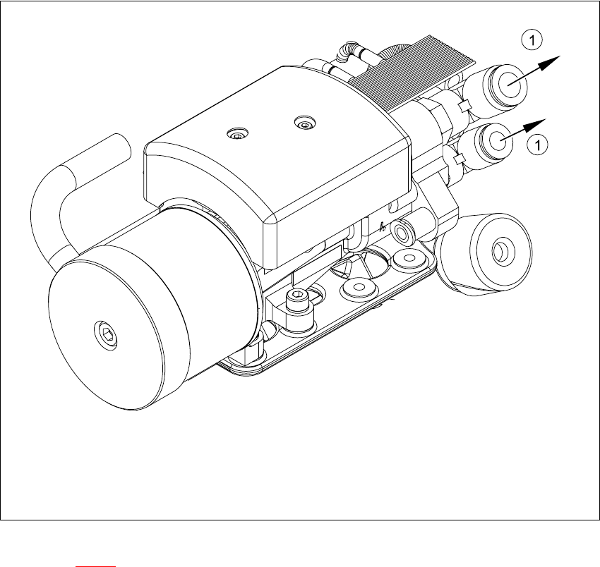
Fig. 7.5 - 2 Collect&place head - compressed air connections
Key to Fig. 7.5 - 2
(1) Compressed air connections
7
Æ Remove the black compressed air hose (1) from the compressed air connector.
7 DLM2 Collect&Place Head HS-60 Service Manual
7.5 Replacing the collect&place head / DLM2 (00367770-01) 03/2003 US Issue
266
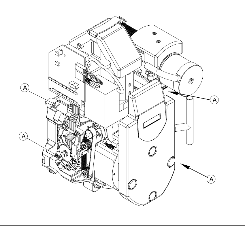
Æ Undo the four hexagon socket-head screws (M4x16) (item A in 7.5 - 3).
7
Fig. 7.5 - 3 Fixing the collect&place head on the head mount
Æ Carefully pull the collect&place head away from the parallel pins (Item 4 in Fig. 7.5 - 4) on the
head mount and remove it from the placement system.