Service Manual HS60.pdf - 第272页
7 DL M2 Co llec t &P lace Head H S-6 0 S erv ic e Manu al 7. 6 D is mant lin g / f i tti ng th e fro nt pa rt of t he col lec t& pl ac e h e ad 03/ 2 003 U S I ssue 270 . 7 F ig. 7. 6 - 1 Di sma nt lin g / fi tti…
HS-60 Service Manual 7 DLM2 Collect&Place Head
03/2003 US Issue 7.6 Dismantling / fitting the front part of the collect&place head
269
7.6 Dismantling / fitting the front part of the
collect&place head
7.6.1 Tools and equipment
– Set of DIN 911 Allen keys
– SITEST program
– Adjustment instructions
CAUTION Be careful with the glass scales in the sleeves. They are very fragile. 7
7.6.2 Dismantling the front part of the collect&place head
Æ Switch the placement system off and secure it to prevent switching on again as described in
Section 7.4
, page 261.
Æ Remove the connecting cable plugs from sockets X9, X13, X14 on the head board
(see Fig. 7.5 - 1
).
Æ Remove the pneumatic hose.
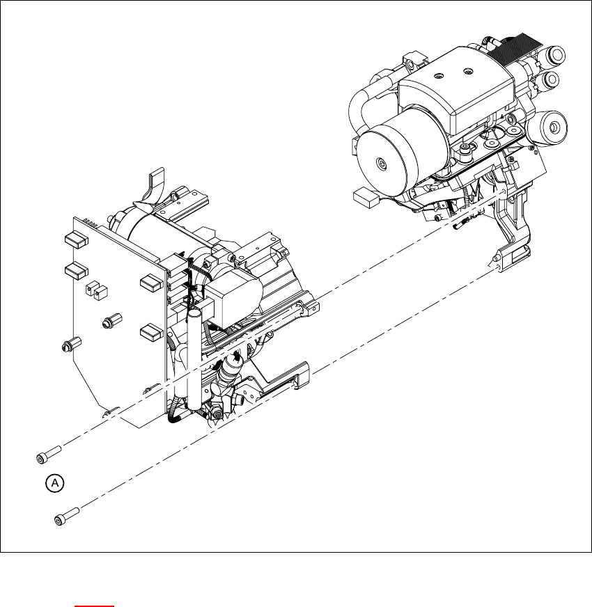
Æ Undo the four M3x16 hexagon socket head screws (item A in Figs. 7.6 - 1 and 7.6 - 2).
CAUTION When you undo the last screw, hold the collect&place head so that it
does not accidentally drop off the back part. 7
CAUTION When you remove the front part of the collect&place head, make sure
that the star is pivoted roughly 15° away from the vertical sleeve position. Otherwise the valve
plunger will remain attached to the valve actuator. 7
Æ Lift the front part of the collect&place head away from the parallel pins on the back part and
place on a soft, clean surface.
7 DLM2 Collect&Place Head HS-60 Service Manual
7.6 Dismantling / fitting the front part of the collect&place head 03/2003 US Issue
270
. 7
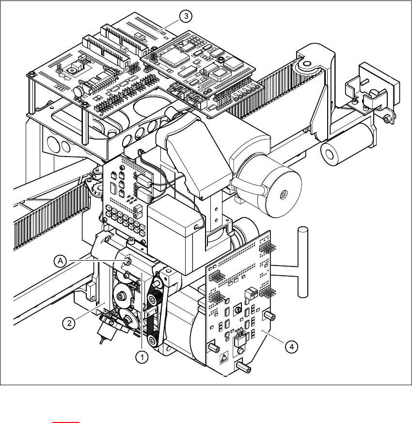
Fig. 7.6 - 1 Dismantling / fitting the front part of the collect&place head - part 1
Key to Fig. 7.6 - 1
(1) Front part of the collect&place head
(2) Back part of the collect&place head
(3) Head board
(4) Intermediate distribution board
(A) Loosen the M4x16 hexagon socket-head screw 7