Service Manual HS60.pdf - 第273页
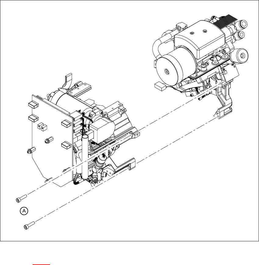
HS -60 Se rvic e Ma nual 7 DLM2 Co l lect&Plac e Head 03/2 003 US Issue 7.6 Dis mantli ng / fit tin g the fr on t part of the co lle ct&p lace he ad 271 7 F ig. 7 .6 - 2 D isma ntlin g / f itting th e fro nt part…
7 DLM2 Collect&Place Head HS-60 Service Manual
7.6 Dismantling / fitting the front part of the collect&place head 03/2003 US Issue
270
. 7
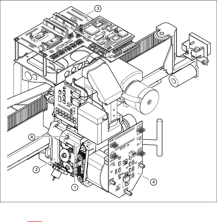
Fig. 7.6 - 1 Dismantling / fitting the front part of the collect&place head - part 1
Key to Fig. 7.6 - 1
(1) Front part of the collect&place head
(2) Back part of the collect&place head
(3) Head board
(4) Intermediate distribution board
(A) Loosen the M4x16 hexagon socket-head screw 7
7 DLM2 Collect&Place Head HS-60 Service Manual
7.6 Dismantling / fitting the front part of the collect&place head 03/2003 US Issue
272
7.6.3 Fitting the front part of the collect&place head
7
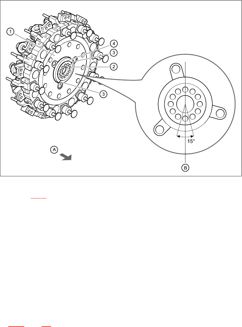
Fig. 7.6 - 3 Installation position of the distributor plate
Key to Fig. 7.6 - 3
(1) Star
(2) Distributor plate
(3) Parallel pins
(4) Raised part of the distributor plate
7
(A) Arrow points towards the back part
(B) Vertical sleeve position
7
Æ Grease the O-rings with Unisilikon.
Æ Push the small O-ring onto the tube.
Æ Place the large O-ring in the hole for the distributor block (item 7 in Fig.
7.2 - 1
, page 250).
Æ Check that the O-rings are seated correctly.